【
7-24
】
ELECTRICAL SYSTEM
11.
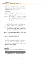
Speedometer
The
speedometer
shows
approximate
vehicle
speed.
To
change
between
“mph”
and
“km/h”,
press
“Set”
and
“Mode”
button
simultaneously
for
more
than
2
seconds.
The
display
unit
of
ODO/TRIP
meters
changes
at
the
same
time.
12.
ODO/TRIP
meter
This
display
has
two
functions,
odometer
and
2
trip
meters.
Press
“Mode”
button
to
change
the
display.
●
Odometer:
The
odometer
registers
the
total
distance
which
the
vehicle
has
been
ridden.
●
Trip
meter:
The
2
Trip
meter
can
be
reset
and
recorded
two
kinds
of
distance.
For
example,
Trip
A
can
register
the
trip
distance
and
Trip
B
can
record
the
distance
between
adding
fuels.
Press
more
than
2
seconds
to
reset
the
Trip
to
“0”.
13.
Clock/Hour/Tacho/Temp
Meter
This
display
has
four
functions,
Clock,
Hour,
Tacho
and
Temp
meter.
To
change
the
display,
press
“Set”
button
shortly.
●
Clock:
Display
the
time
in
12
‐
hour.
To
set
the
clock,
change
to
Clock
mode
and
press
“Set”
button
more
than
2
seconds.
The
display
starts
to
blink.
Press
“Mode”
to
change
minute
and
hour.
Press
“Set”
to
adjust.
●
Hour :
The
hour
meter
indicates
the
total
time
that
the
vehicle
is
used.
●
Tacho
Meter:
Tacho
meter
displays
the
engine
RPM.
●
Temp:
This
shows
the
engine
temperature.
14.
Fuel
Meter
The
fuel
meter
shows
the
remaining
amount
of
fuel
in
the
fuel
tank.
It
displays
8
segments
when
the
fuel
tank
is
full.
The
bottom
segment
blinks
when
the
fuel
level
drops.
Please
add
fuel
when
the
fuel
alert
comes
on.
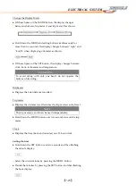
Operating
Procedure
Initial
Display
●
When
the
ignition
switch
is
set
to
ON,
all
LCD
light
up
for
two
seconds.
NOTE
○
Since
the
clock
resets
to
“
1:00
”
,
it
will
need
to
be
readjusted.
Summary of Contents for DL-702 2008
Page 1: ...FOREWORD INDEX 0 0...
Page 41: ...3 11 BRAKE...
Page 180: ...6 70 ENGINE Install the starter motor...
Page 201: ...7 21 COOLING AND LUBRICATION SYSTEM Engine Lubrication System Chart...
Page 202: ...7 22 COOLING AND LUBRICATION SYSTEM Engine Lubrication System 1 2 3 1 2 3 1 2 3...
Page 203: ...7 23 COOLING AND LUBRICATION SYSTEM 1 2 3...
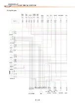
Page 235: ...7 32 ELECTRICAL SYSTEM Wiring Diagram...
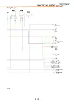
Page 236: ...7 33 ELECTRICAL SYSTEM Wiring Diagram...
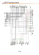
Page 237: ...7 34 7 34 ELECTRICAL SYSTEM ELECTRICAL SYSTEM...
Page 238: ...7 35 ELECTRICAL SYSTEM NOTE...
Page 240: ...9 2 PERIODIC MAINTENANCE...
Page 246: ...9 8 PERIODIC MAINTENANCE Intake Side...
Page 247: ...9 9 PERIODIC MAINTENANCE Exhaust Side Side...
Page 270: ...9 32 PERIODIC MAINTENANCE 1 2 3 4 18 19 12 16 17 21 13 14 15 22 23 5 6 7 8 9 12 10 11 20...

