【
3-7
】
BRAKE
Installation
●
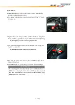
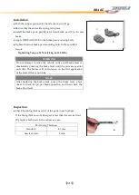
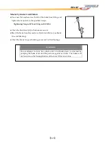
Install the master cylinder in the reverse order of removal. Pay
attention to the following points.
● The master cylinder clamp must be in
stalled with the "UP" mark
[C] upwards.
● Tighten the upper clamp bolt first, and then the lower clamp bolt.
There will be a gap at the lower part of the clamp after tightening.
Tightening Torque: 9 N-m (0.90 kg-m, 6.5 lb-ft )
● Use a new flat was
her on each side of the brake hose fitting, and
tighten the banjo bolt.
Tightening Torque: 25N-m (2.5kg-m, 18.0 lb-ft)
● Bleed the brake line after master cylinder installation (see Brake
Line Air Bleeding).
● Check the brake for good braking power and
no fluid leakage.
WARNING
Do not attempt to drive the vehicle until a full brake lever is
obtained by pumping the brake lever until the pads are against
each disc. The brakes will not function on the first application
of the lever if this is not done.
C
Summary of Contents for DL-702 2008
Page 1: ...FOREWORD INDEX 0 0...
Page 41: ...3 11 BRAKE...
Page 180: ...6 70 ENGINE Install the starter motor...
Page 201: ...7 21 COOLING AND LUBRICATION SYSTEM Engine Lubrication System Chart...
Page 202: ...7 22 COOLING AND LUBRICATION SYSTEM Engine Lubrication System 1 2 3 1 2 3 1 2 3...
Page 203: ...7 23 COOLING AND LUBRICATION SYSTEM 1 2 3...
Page 235: ...7 32 ELECTRICAL SYSTEM Wiring Diagram...
Page 236: ...7 33 ELECTRICAL SYSTEM Wiring Diagram...
Page 237: ...7 34 7 34 ELECTRICAL SYSTEM ELECTRICAL SYSTEM...
Page 238: ...7 35 ELECTRICAL SYSTEM NOTE...
Page 240: ...9 2 PERIODIC MAINTENANCE...
Page 246: ...9 8 PERIODIC MAINTENANCE Intake Side...
Page 247: ...9 9 PERIODIC MAINTENANCE Exhaust Side Side...
Page 270: ...9 32 PERIODIC MAINTENANCE 1 2 3 4 18 19 12 16 17 21 13 14 15 22 23 5 6 7 8 9 12 10 11 20...

