DINO 105T
13
OPERATION OF THE SAFETY DEVICES
1.
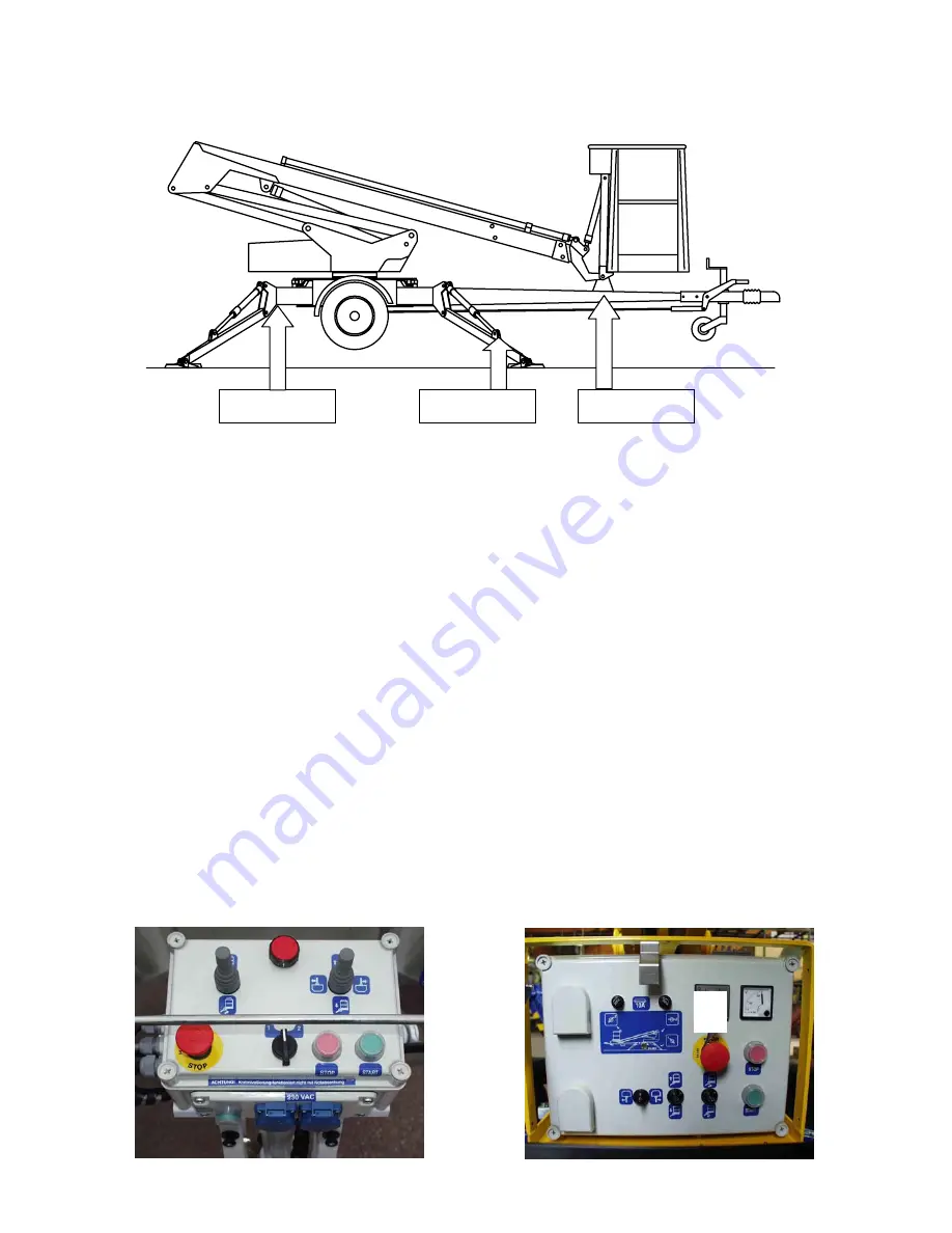
Limit switch on the boom support RK3
The safety limit switch prevents the operation of the outriggers if the boom does not rest on the
transport support. The switch is located on the parking support of the towbar.
2.
Limit switches for outriggers RK4 - RK7
The safety limit switches prevent the manoeuvring of the boom if the outriggers are not in the
support position. The switches are located on the outriggers.
3.
Limit switches for outriggers RK11 - RK14
The safety limit switches prevent the manoeuvring of the boom unless the outriggers are not steady
supported on the ground. The switches are located on the outriggers, one at each outrigger.
4.
Emergency stop button
Stops immediately all movements and shuts off the power unit. The emergency stop pushbutton
must be pulled up before the power unit can be restarted (buttons 3).
Ensure the operation of the safety devices - do not lock the chassis panel (OK1) cover with
key while the lift is in operation.
RK4-RK7
RK11-RK14
RK3
3
3
Summary of Contents for DINO 105T
Page 2: ...DINO 105T 2...
Page 3: ...DINO 105T 3 OPERATING INSTRUCTIONS...
Page 4: ...DINO 105T 4 Valid from serial number 5336...
Page 8: ...DINO 105T 8 REACH DIAGRAM 120 kg...
Page 34: ...DINO 105T 34 LUBRICATION PLAN...
Page 37: ...DINO 105T 37...
Page 69: ...DINO 105T 69 ELECTRIC DIAGRAM 5336...
Page 70: ...DINO 105T 70...
Page 71: ...DINO 105T 71...
Page 72: ...DINO 105T 72...
Page 73: ...DINO 105T 73...
Page 74: ...DINO 105T 74...
Page 75: ...DINO 105T 75 Notes...
Page 77: ...DINO 105T 77 HYDRAULIC DIAGRAM 5336...
Page 78: ...DINO 105T 78 Notes...

