background image

DINO 105T 


20

 
5.


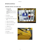
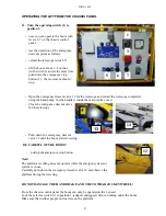
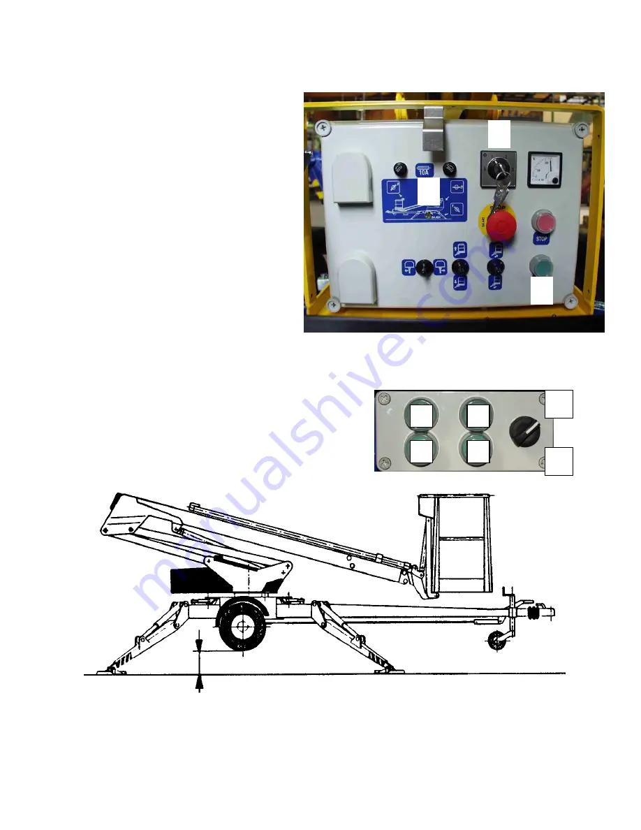
To access the operating controls open the cover on the chassis. 


6.


Turn the selector switch (1) to 
position 1 


7.


Start the engine with button 2 (green). 


8.


Lower the front support outriggers (3 
and 4, on the towbar side) 


9.


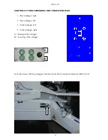
Lower the rear support outriggers (1 
and 2, do not damage the towbar 
jockey wheel) 


10.


Level the chassis with the outriggers 
with the help of the level indicator. 


the signal light 4 in the main centre is lit while the 
limit switches on the outriggers are closed 


make sure all outriggers are firmly supported on the 
ground


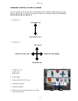
Make sure that the wheels are off the ground. 

1

2

3

4

A

B

2

4

Summary of Contents for DINO 105T

Page 1: ...DINO 105T OPERATING INSTRUCTIONS Raikkolantie 145 FI 32210 LOIMAA T 358 2 762 5900 F 358 2 762 7160 dino dinolift com www dinolift com...

Page 2: ...DINO 105T 2...

Page 3: ...DINO 105T 3 OPERATING INSTRUCTIONS...

Page 4: ...DINO 105T 4 Valid from serial number 5336...

Page 5: ...STOPPING OF THE POWER UNIT 23 EMERGENCY DESCENT SYSTEM 25 SPECIAL INSTRUCTIONS FOR WINTER USE 26 MEASURES TO BE TAKEN AT THE END OF THE WORKING DAY 27 PREPARING THE LIFT FOR TRANSPORT 28 CONNECTION TO...

Page 6: ...OL CENTRE UCB SWITCHES 64 CONTROL CENTRE OCB CONTROL OF OUTRIGGERS 64 CONTROL CENTRE PLCB QUICKSILVER SWITCHES FOR LEVELLING OF THE PLATFORM 64 VALVES CHASSIS 65 VALVES TURNING DEVICE 65 LIMIT SWITCHE...

Page 7: ...010 kg axle load 940 kg towbar load 70 kg Max allowed load on platform 120 kg Max number of persons additional load 1 person 40 kg Max allowed sideways load caused by persons 200 N Max lateral inclin...

Page 8: ...DINO 105T 8 REACH DIAGRAM 120 kg...

Page 9: ...ty 40 kg of additional load however the total load must not exceed one hundred twenty 120 kg The platform may only be operated when the chassis is well supported and the wheels are off the ground The...

Page 10: ...warning lights or fencing Also observe the regulations of the Road Traffic Act Beware of the live aerial power lines in the area observe the minimum safety distances Keep the lift clean of any dirt w...

Page 11: ...inspection If the lift is operated under especially severe conditions the inspection intervals should be shorter than mentioned above The general operating condition of the lift and the due operation...

Page 12: ...ing carried out in accordance with the instructions and have the defects affecting the safety been checked as repaired Inspection protocol 3 Structure Visual inspection and operational test General co...

Page 13: ...ion The switches are located on the outriggers 3 Limit switches for outriggers RK11 RK14 The safety limit switches prevent the manoeuvring of the boom unless the outriggers are not steady supported on...

Page 14: ...platform 3 controlling the boom from the chassis 2 Start button 3 Emergency stop button 4 Signal light for limit switches on the axle 5 Control lever for turning 6 Control lever for boom system 7 Cont...

Page 15: ...L 1 Rear outrigger right 2 Rear outrigger left 3 Front outrigger left 4 Front outrigger right A Raising of the outrigger B Lowering of the outrigger Level the chassis with the outriggers with the help...

Page 16: ...n the platform The cover must not be locked while the lift is in operation 1 Control lever 2 Control lever 3 Emergency stop push to stop pull to reset 4 Sound signal 5 Socket outlet 230VAC 2 pcs 6 Sto...

Page 17: ...try to find out the reason for the reduced stability and the direction of its effect Warn other people on the work site using the alarm signal 2 Reduce the outreach to the side by retracting the tele...

Page 18: ...n and inclination of the surface on the support the support outriggers must not slip on the surface the operation is prohibited if the lift is not properly supported and in a level position Ground mat...

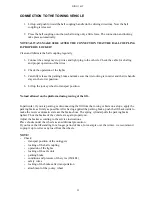
Page 19: ...wing vehicle 3 Turn and lower the outriggers to support position 4 Connection of power supply to the lift connect the mains cable to the power supply for maximum out of the electric motor the voltage...

Page 20: ...4 on the towbar side 9 Lower the rear support outriggers 1 and 2 do not damage the towbar jockey wheel 10 Level the chassis with the outriggers with the help of the level indicator the signal light 4...

Page 21: ...he handle is inside the main centre cover Close the emergency descent valve for the telescope Push down the emergency descent valve 12 until the boom starts lowering BE CAREFUL OF THE BOOM pull up the...

Page 22: ...nt speeds from the platform control panel Turn the switch 8 and at the same time move the contol levers 1 and 2 on the platform control panel in the desired movement direction to the left 1 speed to t...

Page 23: ...ded make sure that the platform does not lower of itself while the operating controls are not being used Under cold conditions let the engine run for a while without load to raise the temperature of t...

Page 24: ...arly during the operation taking into account the weather and ground conditions When moving the platform remember the following be careful of the high voltage power lines do not exceed the max allowed...

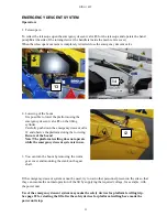
Page 25: ...nt valve 12 and observe the platform during the lowering Beware of the boom Note The platform levelling does not operate while the emergency descent system is in use 3 You can turn the boom by removin...

Page 26: ...before starting the movements start with a few movements to warm up oil in the cylinders and to ensure proper operation of the valves check that the limit switches and the emergency descent devices a...

Page 27: ...owbar extend the telescope until the boom gets locked in its catch The limit switch on the transport support prevents the operation of the support outriggers if the platform does not lie steady on the...

Page 28: ...e operation of the support outriggers if the platform does not lie steady on the support 4 Close the cover of the platform control panel 5 Turn the selector switch 1 outriggers to position 1 6 Lift th...

Page 29: ...load allowed on the platform during towing of the lift In particular if you are parking or disconnecting the lift from the towing vehicle on a slope apply the parking brake as firmly as possible Afte...

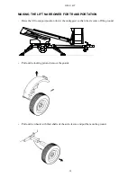
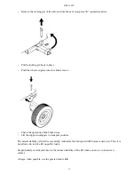
Page 30: ...R TRANSPORTATION Raise the lift to support position lower the outriggers so that wheels come off the ground Pull out the locking pin and remove the guards Pull out the wheels with their shafts of the...

Page 31: ...he operation of the brake wires Lift the support outriggers to transport position The lateral stability of the lift is essentially reduced as the transport width becomes narrower Thus it is not allowe...

Page 32: ...sed next time Do not spill oil on the ground Keep the lift clean especially the platform Clean up the lift before service and inspection Use genuine spare parts Support the platform boom articulated a...

Page 33: ...s and adjust the pads if necessary 4 Service every six months change the hydraulic oil and the filter cartridge check the wheel bolts for tightness 90 Nm grease the bearing and the gear ring of the tu...

Page 34: ...DINO 105T 34 LUBRICATION PLAN...

Page 35: ...ylinder 9 Sliding surfaces of the telescope silicon oil 10 Jockey wheel slide and threads TWICE A YEAR 11 Spherical bearing of the telescope cylinder 12 Frame part of the outriggers 13 Overrun device...

Page 36: ...ure the stroke and observe in a few minutes time that the stroke does not change Note Drive the boom to an almost vertical position 4 To check the tightness of the load regulation valve on the platfor...

Page 37: ...DINO 105T 37...

Page 38: ...times in the course of the test run Adjustment of the bearing clearance The wheel bearings are lubricated for life and do not need any service The bearings need no additional lubrication and cannot b...

Page 39: ...he platform i e neither the quicksilver switch box nor its attachment are damaged Remove the seal and open the cover of the box Unscrew the locking nuts of the quicksilver switch adjustment screws Bas...

Page 40: ...rsonnel of the dealer SCHEDULE FOR REGULAR SERVICING 1 Clean the lift thoroughly before the service The hydraulic and electric appliances must not be dismantled if they are not clean Any contaminants...

Page 41: ...the draining hose and discharge the oil in a waste oil reseptacle Clean and rinse the oil tank with a suitable agent Put the draining plug in place Replace the filter cartridge in connection with ever...

Page 42: ...ort outriggers lower slightly the outriggers swing the outriggers laterally and check the joints for play replace the slide bearing and pin if necessary lubricate the joints refer to the lubrication p...

Page 43: ...ton rod and tightness of the connections drive the lifting cylinder to its lowest positionfrom the chassis control panel and check the tightness of the connections retract and extend the telescope cyl...

Page 44: ...g bearing play by turning Max permissible play is about 1 mm check the tightening torque of the attachment bolts 150 Nm M12 If you have to unscrew or tighten the attachment bolts do not forget to use...

Page 45: ...f the axle unit check condition of the rubber absorbers and torsion arms 9 Check the safety devices check the attachment and the external condition of the limit switches towbar 1 pcs support outrigger...

Page 46: ...ssure secure the new setting with a seal 12 Check the operating controls on the platform check the overall condition of the electric appliances inside the box and spray with moisture repellent if nece...

Page 47: ...adjust the brakes put the wheels in place and tighten the wheel bolts 90 Nm check the tyre pressures 2 3 bar check the free movement of the overrun brake and the parking brake check the safety wires 1...

Page 48: ...ted in a maintenance inspection which is carried out on the works site from time to time if possible once a week VNp 629 94 11 12 13 ja 14 Keep a journal of notable shortcomings and defects and inform...

Page 49: ...m the platform and the chassis control panels test the operation of the emergency descent system test the alarm signal check the warning and signal lights check the operation and cleanliness of the li...

Page 50: ...breaches are the possible repair weldings duly executed check that the platform does not drift refer to the service instruction check that the outriggers do not drift refer to the service instruction...

Page 51: ...platform and extend the telescope keeping the boom level Turn the boom round a few times stop at the initial position and check that the distance between the ground and the outriggers has not changed...

Page 52: ...ks trace of corrosion or chafing at the clamps check that the pipes are properly fastened connections check the hose and pipe connections for leaks inspect thoroughly the electric system check that th...

Page 53: ...condition of the power transmission chain electric cables and hydraulic hoses check the play and attachment of the gliding surfaces on the boom check the platform general condition check that there a...

Page 54: ...ock the movement of the boom after the test run make sure that the test loading has not caused any defects such as fractures or permanent deformations of dangerous nature on the steel structures or ot...

Page 55: ...he above mentioned test loading and the subsequent inspection have been completed without any remarks concerning the structure or stability of the lift the lift may be used in accordance with the perm...

Page 56: ...he contact piece is out reset the point with the tip of a screwdriver Spray with moisture repellent and test the operation of the pushbutton Close the box carefully The safety relay for platform level...

Page 57: ...with moisture repellent 6 The boom drifts slowly downwards The lock valve i e the pressure activated check valve leaks Disconnect and clean the valve Check the condition of the o rings Install the val...

Page 58: ...itch is in position 1 The boom does not rest on the transport support Drive the boom onto the support The electric valve of the boom outriggers must not operate remains in the centre position For reme...

Page 59: ...ty Replace the shock absorber Reverse automatics the brake shoe jams Change the brake shoe in the carrier 15 The brakes drag only one of the wheels brakes Brake units wrongly adjusted Readjust the bra...

Page 60: ...be replaced Always when you change brake shoes replace all shoes on the axle Always when assembling the brakes make sure to install the springs the brake shoes and the expander in the right way When...

Page 61: ...ver valve and telescope 1 and 4 change over valve and turning 1 and 3 platform valve and cartridge valve 4 and 6 Press the pin at the end of the electric valves If the movements operate the fault is i...

Page 62: ...the limit switch RK3 switches off the voltage from the relay K8 the telescope out operation is switched off K7 blocking relay of II speed The use of II speed is blocked during levelling of the platfor...

Page 63: ...r limit switches are closed T1 POWER SOURCE 230VAC 12VDC 10A Supplies the control voltage for the control system of the lift VM1 VOLTAGE METER Indicates the power supply voltage in volts VAC MAIN CONT...

Page 64: ...TCH FOR OUTRIGGERS For selection of movement direction raising lowering S20 NON LOCKING PUSHBUTTON FOR SELECTION OF OUTRIGGER 1 S21 NON LOCKING PUSHBUTTON FOR SELECTION OF OUTRIGGER 2 S22 NON LOCKING...

Page 65: ...RIGGERS CARTRIDGE VALVE VALVES TURNING DEVICE 1A SELECTOR VALVE FOR OUTRIGGERS 1B SELECTOR VALVE FOR BOOM 2A OPERATIONAL VALVE PLATFORM LEVELLING BACKWARDS 2B OPERATIONAL VALVE PLATFORM LEVELLING FORW...

Page 66: ...trigger is turned to support position RK7 SUPPORT POSITION LIMIT SWITCH FOR OUTRIGGER 4 The limit switch closes as the outrigger is turned to support position RK11 LIMIT SWITCH FOR OUTRIGGER 1 The lim...

Page 67: ...transport support K10 614 LCB 48 650 Change over relay Blocks the boom up movement while the boom rests on the transport support M1 134 47 816 Electric motor AC electric motor Q1 233 414 LCB 48 2316...

Page 68: ...ch Turning of platform left right S17 425 LCB 48 616 48 1007 Lever switch Raising lowering of the boom S18 432 LCB 48 616 48 1007 Lever switch Telescope in out S19 636 OCB 48 2304 48 2302 Turn switch...

Page 69: ...DINO 105T 69 ELECTRIC DIAGRAM 5336...

Page 70: ...DINO 105T 70...

Page 71: ...DINO 105T 71...

Page 72: ...DINO 105T 72...

Page 73: ...DINO 105T 73...

Page 74: ...DINO 105T 74...

Page 75: ...DINO 105T 75 Notes...

Page 76: ...relief valve 11 47 2742 Pressure relief valve 12 47 2722 Load regulating valve 13 47 2273 Hydraulic motor 14 15 47 2743 Check valve 16 47 2293 Power unit 17 47 171 Pressure filter 18 47 190 Breather c...

Page 77: ...DINO 105T 77 HYDRAULIC DIAGRAM 5336...

Page 78: ...DINO 105T 78 Notes...

Reviews: