DINO 105T
31
-
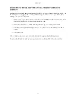
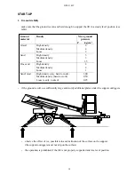
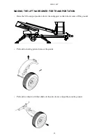
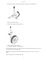
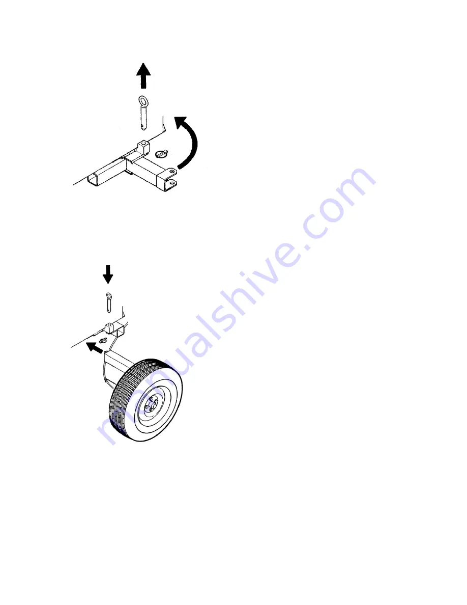
Remove the locking pin of the axle and turn the axle crosspiece 90° counterclockwise.
-
Put the locking pin back in place
-
Push the wheels in place into the shorter sleeve.
-
Check the operation of the brake wires.
-
Lift the support outriggers to transport position.
The lateral stability of the lift is essentially reduced as the transport width becomes narrower. Thus it is
not allowed to tow the lift on public roads.
Be particularly careful and observe the reduced stability of the lift when you move on an uneven
surface.
Always, when possible, use the greater track width.
Summary of Contents for DINO 105T
Page 2: ...DINO 105T 2...
Page 3: ...DINO 105T 3 OPERATING INSTRUCTIONS...
Page 4: ...DINO 105T 4 Valid from serial number 5336...
Page 8: ...DINO 105T 8 REACH DIAGRAM 120 kg...
Page 34: ...DINO 105T 34 LUBRICATION PLAN...
Page 37: ...DINO 105T 37...
Page 69: ...DINO 105T 69 ELECTRIC DIAGRAM 5336...
Page 70: ...DINO 105T 70...
Page 71: ...DINO 105T 71...
Page 72: ...DINO 105T 72...
Page 73: ...DINO 105T 73...
Page 74: ...DINO 105T 74...
Page 75: ...DINO 105T 75 Notes...
Page 77: ...DINO 105T 77 HYDRAULIC DIAGRAM 5336...
Page 78: ...DINO 105T 78 Notes...

