DINO 105T
45
7.
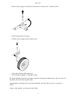
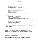
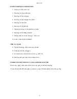
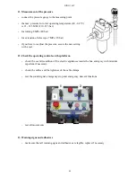
Check the overrun
-
attachment of the overrun
-
clearance
-
condition of the towball coupling
-
condition of the locking device
-
check that the overrun operates smoothly:
-
stop the carriage by applying the parking brake
-
push in the ball coupling with its push rod
-
the push rod and the ball coupling must return by themselves to their outer initial positions
forced by the gas cushion in the hydraulic shock absorber.
8.
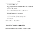
Check the axle unit and the
suspension system
-
check the attachment of the axle
unit
-
check condition of the rubber
absorbers and torsion arms
9.
Check the safety devices
-
check the attachment and
the external condition of
the limit switches.
-
towbar (1 pcs)
-
support outriggers (8 pcs)
10.
Operation of the safety devices when controlled from the chassis control panel
-
lower the outriggers (wheels off the
ground)
-
raise the platform slightly from the
transport position
-
the outriggers must not operate in any
position of the selector switch
-
raise the boom and test the following:
-
emergency stop
-
emergency descent; lowering of the
boom
-
bring the boom to transport position and
raise the outriggers.
-
the boom must not operate in any
position of the selector switch
5
6
7
1
11
Summary of Contents for DINO 105T
Page 2: ...DINO 105T 2...
Page 3: ...DINO 105T 3 OPERATING INSTRUCTIONS...
Page 4: ...DINO 105T 4 Valid from serial number 5336...
Page 8: ...DINO 105T 8 REACH DIAGRAM 120 kg...
Page 34: ...DINO 105T 34 LUBRICATION PLAN...
Page 37: ...DINO 105T 37...
Page 69: ...DINO 105T 69 ELECTRIC DIAGRAM 5336...
Page 70: ...DINO 105T 70...
Page 71: ...DINO 105T 71...
Page 72: ...DINO 105T 72...
Page 73: ...DINO 105T 73...
Page 74: ...DINO 105T 74...
Page 75: ...DINO 105T 75 Notes...
Page 77: ...DINO 105T 77 HYDRAULIC DIAGRAM 5336...
Page 78: ...DINO 105T 78 Notes...

