DINO 105TL
24
S20
S18
S16
S17
H3
Q1
S1
Vi
S2
S3
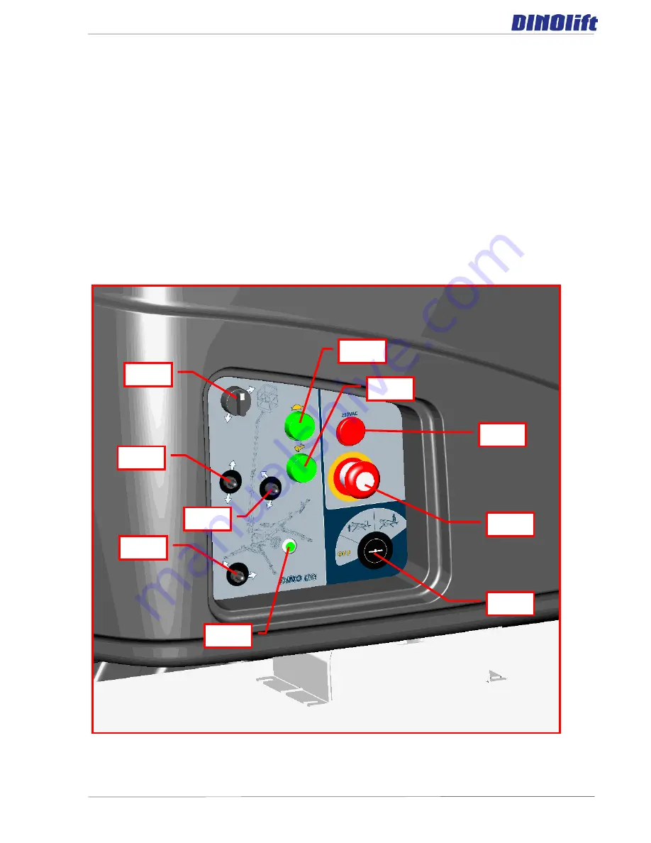
2. Drive the lift to the inspected lifting site
- apply the parking brake
- disconnect the lift from the towing vehicle
3. Connection of power supply to the lift
- connect the mains cable to the power supply
- for maximum out of the electric motor the voltage must 230 VAC (-10 % +6 %), the
frequency must be 50 Hz and rating of the fuse 10A (the length of the connecting cable
has some effect)
4. Turn the selector switch (Q1) to position LCB – chassis centre
5. Start the engine from the pushbutton S2 or S3
Summary of Contents for DINO 105TL
Page 2: ...DINO 105TL 2 ...
Page 3: ...DINO 105TL 3 ORIGINAL OPERATING INSTRUCTIONS Valid from serial number 10196 ...
Page 6: ...DINO 105TL 6 HYDRAULIC DIAGRAM 10189 81 23 1 NOTES 82 ...
Page 8: ...DINO 105TL 8 2 REACH DIAGRAM ...
Page 9: ...DINO 105TL 9 3 DIMENSION DRAWING ...
Page 35: ...DINO 105TL 35 o that the driving device is disconnected from the wheel ...
Page 38: ...DINO 105TL 38 18 3 LUBRICATION PLAN 1 2 3 4 5 5 6 7 8 10 9 11 12 ...
Page 41: ...DINO 105TL 41 ...
Page 53: ...DINO 105TL 53 19 1 1 SAMPLE OF INSPECTION PROTOCOL FOR THE ACCESS PLATFORM ...
Page 54: ...DINO 105TL 54 ...
Page 69: ...DINO 105TL 69 21 1 NOTES ...
Page 73: ...DINO 105TL 73 23 ELECTRIC DIAGRAM 105TL 10196 ...
Page 74: ...DINO 105TL 74 ...
Page 75: ...DINO 105TL 75 ...
Page 76: ...DINO 105TL 76 ...
Page 77: ...DINO 105TL 77 ...
Page 78: ...DINO 105TL 78 ...
Page 79: ...DINO 105TL 79 ...
Page 80: ...DINO 105TL 80 ...
Page 81: ...DINO 105TL 81 HYDRAULIC DIAGRAM 10189 ...
Page 82: ...DINO 105TL 82 23 1 NOTES ...


