25
4.1.4.
Check the driving device
Check that the driving device is operating correctly.
The platform must travel straight, when the lift is being transferred using the driving device.
Check the load holding valves of the driving device for tightness.
4.1.5.
Check the condition and attachment of the battery and the wiring.
Check visually the condition and attachment of the battery and the visible wiring.
4.1.6.
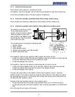
Check the operation and condition of the platform's levelling system
The platform is levelled by means
of a so-called slave cylinder
system, where the master cylinder
under the platform controls the
slave cylinder. The platform keeps
its level position only if the valves
in the system are tight.
21,5 Mpa
215 bar
3100 psi
MP
MV
T
P
MP
MV
21,5 Mpa
215 bar
3100 psi
The levelling system comprises the following parts:
1. Master cylinder
2. Slave cylinder
3. Load regulation valve
4. Double load regulation valve (8A and 8B)
5. Electric directional valve
If the platform, viewed by the operator, drifts forwards, the reason can be:
• a leak in the slave cylinder's double load regulation valve (on the piston rod side) towards
the electric directional valve (which is by design not tight)
• an internal leakage in the cylinder
If the platform, viewed by the operator, drifts backwards, the reason can be:
• a leak in the load regulation valve (4) on the piston (bottom) side of the slave cylinder
towards the electric directional valve (5) (which is by design not tight)
• an internal leakage in the cylinder
The leak will cause drifting of the platform until the load regulation valve (3) under the
platform closes. The closing is caused by dropping of the pressure on the piston rod side to
the opening ratio, which is 5:1 If the valves are not tight, refer to the service instructions for
checking the load regulation valves.
Settings of the load regulation valves in the levelling system:
• the opening pressure of the double load regulation valves (4) is 21.5 MPa (215 bar)
• the opening pressure of the load regulation valve (3) under the platform is 21.5 MPa (215
bar)
Do not change the set values of the valves.
Summary of Contents for DINO 160XT II
Page 2: ......
Page 19: ...19 6 9 7 11 7 8 1 5 5 3 2 12 3 4 10 13 2 2 LUBRICATION PLAN 14...
Page 79: ...79...
Page 80: ...80 Maintenance instructions DINO 160XT II 180XT II 210XT II...
Page 81: ...81...
Page 82: ...82 Maintenance instructions DINO 160XT II 180XT II 210XT II...
Page 83: ...83...
Page 84: ...84 Maintenance instructions DINO 160XT II 180XT II 210XT II...
Page 85: ...85...
Page 86: ...86 Maintenance instructions DINO 160XT II 180XT II 210XT II...
Page 87: ...87...
Page 88: ...88 Maintenance instructions DINO 160XT II 180XT II 210XT II...
Page 89: ...89...
Page 90: ...90 Maintenance instructions DINO 160XT II 180XT II 210XT II...
Page 91: ...91...
Page 92: ...92 Maintenance instructions DINO 160XT II 180XT II 210XT II...
Page 93: ...93...
Page 94: ...94 Maintenance instructions DINO 160XT II 180XT II 210XT II...
Page 95: ...95...
Page 96: ...96 Maintenance instructions DINO 160XT II 180XT II 210XT II...
Page 97: ...97...
Page 98: ...98 Maintenance instructions DINO 160XT II 180XT II 210XT II...
Page 99: ...99...
Page 100: ...100 Maintenance instructions DINO 160XT II 180XT II 210XT II...
Page 101: ...101...
Page 102: ...102 Maintenance instructions DINO 160XT II 180XT II 210XT II...
Page 103: ...103...


