3
- Exclusive SWS “Smart Welding Stop” system at the end of
TIG welding. Lifting up the torch without switching off the
arc will introduce a slope down and it will switch off auto-
matically.
- “Energy Saving” function to operate the power source cool-
ing fan and the torch water cooling only when necessary.
- Auto-diagnostic feature for trouble shooting.
- Password-controlled total or partial equipment access.
•
High electrical performance resulting in a reduction in ener-
gy consumption.
•
Remote parameter adjustment directly from WF 793.M feed-
er.
Technical data
The general technical data of the system are summarized in
table 1.
Usage limits (IEC 60974-1)
The use of a welder is typically discontinuous, in that it is made
up of effective work periods (welding) and rest periods (for the
positioning of parts, the replacement of wire and underflush-
ing operations etc. This welder is dimensioned to supply a I
2
max nominal current in complete safety for a period of work of
40/50% of the total usage time. The regulations in force estab-
lish the total usage time to be 10 minutes. The work cycle is
considered to be 40/50% of this period of time. Exceeding the
work cycle allowed could cause a trip switch to trip, which pro-
tects the components inside the welding power source against
dangerous overheating. After several minutes the overheat cut-
off rearms automatically and the welder is ready for use again.
How to lift up the system
Strap the system safely and securely in the slings working from
the bottom, then lift up from the ground.
This welding power source has a robust handle built into the
frame for moving the equipment.
NOTE: These hoisting and transportation devices conform to
European standards. Do not use other hoisting and transpor-
tation systems.
Table 1
Model
DIX PI 3006.M PULS
DIX PI 4006.M PULS
DIX PI 4606.M PULS
MIG-MAG welding
Three-phase input 50/60 Hz
V
400 ± 20%
400 ± 20%
400 ± 20%
Mains supply: Z
max
Ω
0,037
0,028
0,017
Input power @ I
2
Max
kVA
18,8
25,5
32
Delayed fuse (I
2
@ 60%)
A
25
30
40
Power factor / cosφ
0,64 / 0,99
0,66 / 0,99
0,66 / 0,99
Efficiency degree
η
0,83
0,86
0,89
Open circuit voltage
V
63
70
70
Current range
A
10 ÷ 330
10 ÷ 400
10÷500
Duty cycle @ 100% (40°C)
A
280
330
380
Duty cycle @ 60% (40°C)
A
300
370
460
Duty cycle @ X% (40°C)
A
330 (40%)
400 (50%)
500 (50%)
Wires diameter (*)
mm
0,6 ÷ 1,2 (*)
0,6 ÷ 1,6 (*)
0,6 ÷ 1,6 (*)
N° rollers (*)
4 (*)
4 (*)
4 (*)
Power output of feeder motor (*)
W
100 (*)
100 (*)
100 (*)
Rated wire feeding speed (*)
m/min
0,5 ÷ 25 (*)
0,5 ÷ 25 (*)
0,5 ÷ 25 (*)
Spool (*)
Diameter
Weight
mm
kg
Ø300 (*)
15 (*)
Ø300 (*)
15 (*)
Ø300 (*)
15 (*)
Standards
IEC 60974-1 - IEC 60974-5 (*) - IEC 60974-10
Protection class
IP 23 S
IP 23 S
IP 23 S
Insulation class
H
H
H
Dimensions
mm
660 - 515 - 290
660 - 515 - 290
660 - 515 - 290
Weight
kg
35
40
44
(*) On the WF 793.M feeder, fitted separately.
WARNING: This equipment complies with EN//IEC 61000-3-12 provided that the maximum permissible system impedance Z
max
is less than or
equal to 0,037 Ω DIX PI 3006.M PULS - 0,028 Ω DIX PI 4006.M PULS - 0,017 Ω DIX PI 4606.M PULS at the interface point between the user’s
supply and the public system. It is the responsibility of the installer or user of the equipment to ensure, by consultation with the distribution net
-
work operator if necessary, that the equipment is connected only to a supply with maximum permissible system impedance Z
max
less than or
equal to 0,037 Ω DIX PI 3006.M PULS - 0,028 Ω DIX PI 4006.M PULS - 0,017 Ω DIX PI 4606.M PULS.
This system, tested according to EN/IEC 61000-3-3, meets the requirements of EN/IEC 61000-3-11.
Summary of Contents for DIX PI 3006.M PULS
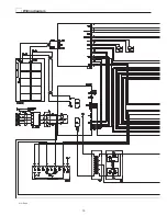
Page 10: ...10 2101EA86 Wiring diagram ...

