background image

5

  MIG-MAG / PULSE MIG / DOUBLE 

PULSE MIG Welding

To begin MIG-MAG / PULSE MIG / DOUBLE PULSE MIG weld-
ing, carry out the following tasks (with the welding power source 
switched off).

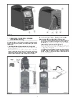
1 - Connecting the gas hose and torch (Fig. B1-B2)

• 

Connect the gas hose to the pressure reducer fitted on the 
cylinder beforehand.

• 

Screw the torch onto the centralised connection on the front 
panel of the feeder and connect the feed (blue) and return 
(red) water hoses for cooling the torch to the respective (blue 
and red) rapid couplings on the front panel of the feeder.

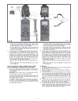
2A - Connecting the cables - Welding with a HAND 
HELD TORCH SET as POSITIVE POLE (Fig. B1)

1)  The feeder - welding power source connecting cable is 

used to connect the welding power source to the feeder.

WARNING: Do not disconnect the wire-feeder until the 
welding power source has been switched off.


Connect up the interconnection cables (power cable, an-
cillary wiring and gas tube) to the special attachments and 
couplings shown in Fig. B1.


The delivery (blue coloured) and return (red coloured) wa-
ter tubes, used for cooling the torch of the welding power 
source, are part of the interconnection cable and should 
be connected as follows:

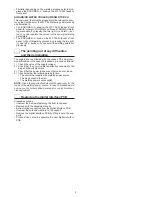
FIG. A

FIG. B1 

2000FC15

Summary of Contents for DIX PI 3006.M PULS

Page 1: ...elding Power Source S C H W E I S S E N W E L D I N G W E L D I N G S C H W E I S S E N S C H W E I S S E N Keep in secure area for future reference Operations manual DIX PI 3006 M PULS DIX PI 4006 M PULS DIX PI 4606 M PULS ...

Page 2: ...al Pulsed on any material and with any gas High welding performance in both MMA and TIG by Lift mode striking Synergic digital control of all welding parameters displayed via the innovative colour display also featuring the follow ing functions Allows less expert operators to regulate all welding param eters in a user friendly way and extremely easily choos ing the type of program on the basis of ...

Page 3: ...uipment NOTE These hoisting and transportation devices conform to European standards Do not use other hoisting and transpor tation systems Table 1 Model DIX PI 3006 M PULS DIX PI 4006 M PULS DIX PI 4606 M PULS MIG MAG welding Three phase input 50 60 Hz V 400 20 400 20 400 20 Mains supply Zmax Ω 0 037 0 028 0 017 Input power I2 Max kVA 18 8 25 5 32 Delayed fuse I2 60 A 25 30 40 Power factor cosφ 0 ...

Page 4: ...ble the system in the following way Assemble the trolley Fixing the cooling unit to the trolley Fixing of the welding power source to the trolley and the cool ing unit electrical and plumbing connections Fitting the feeder unit to the welding power source Connect up the welder to the mains Connect up the wire feeder welding power source intercon nection cable Connect up the welding cables Instruct...

Page 5: ...pid couplings on the front panel of the feeder 2A Connecting the cables Welding with a HAND HELD TORCH SET as POSITIVE POLE Fig B1 1 The feeder welding power source connecting cable is used to connect the welding power source to the feeder WARNING Do not disconnect the wire feeder until the welding power source has been switched off Connect up the interconnection cables power cable an cillary wiri...

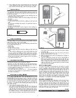
Page 6: ... cable on welding power source side connect up tubes to their rapid couplings blue and red coloured at the back of the coolant system Wire feeder side connecting cable connect the red and blue pipes to their respective bulkhead grommets on the rear panel of the feeder 2 Connect up the earthing system cable to the rapid cou pling marked by a positive symbol and then the relevant ground clamps to th...

Page 7: ... coated rutilic and basic electrodes with diameters ranging from Ø 1 6 mm to Ø 6 mm and devices that the user can adjust for Arc Force Hot Start and Anti sticking functions to avoid the electrodes sticking 1 Connecting the welding cables Fig D Disconnect the welding power source from the mains power supply and connect the welding cables to the output termi nals Positive and Negative of the welding...

Page 8: ...matically 7 When you have finished welding remember to shut the valve on the gas cylinder Table 5 shows the currents to use with the respective elec trodes for TIG DC welding This input is not absolute but is for your guidance only read the electrode manufacturers instruc tions for a specific choice The diameter of the electrode to use is directly proportional to the current being used for welding...

Page 9: ...the cause of the most com mon difficulties In the case of breakdown proceed as follows 1 Check the value of the supply voltage 2 Check that the power cable is perfectly connected to the plug and the supply switch 3 Check that the power fuses are not burned out or loose 4 Check whether the following are defective The switch that supplies the welding power source The plug socket in the wall The weld...

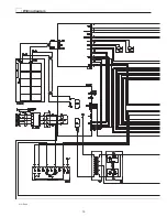
Page 10: ...10 2101EA86 Wiring diagram ...

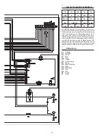
Page 11: ... switch 8 Secondary inductor 9 Pri mary upper IGBT 10 Lower primary IGBT 11 Fan motor 12 Main primary transformer start 13 Main primary trans former end 14 Output diode snubber resistor 15 Prima ry rectifier 16 Secondary rectifier 17 Digital interface PCB 18 Inverter PCB 19 Capacitors PCB 20 Power Source PCB 21 Hall effect transformer 22 Secondary thermostat 23 Main transformer 24 Output diodes sn...

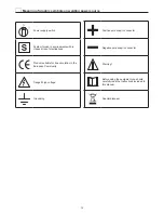
Page 12: ...h in creased risk of electroshock Product suitable for free circulation in the European Community Danger high voltage Grounding Positive pole snap in connector Negative pole snap in connector Warning Before using the equipment you should carefully read the instructions included in this manual Special disposal ...

Page 13: ...LECTION Menu MODE 19 3 SPECIAL FUNCTIONS Menu SET UP Fx 20 4 PRE SETTING 24 5 WELDING 25 6 HOLD 26 7 WIRE LOADING 27 8 DOUBLE FEEDER 27 MMA 28 1 PROGRAM SELECTION Menu PROGRAM MMA 28 2 SPECIAL FUNCTIONS Menu SET UP Fx MMA 28 3 PRE SETTING MMA 30 4 WELDING MMA 31 5 HOLD MMA 32 6 ACTIVATING THE VRD DEVICE MMA 33 TIG LIFT 34 1 SPECIAL FUNCTIONS Menu SET UP Fx TIG LIFT 34 2 PRE SETTING TIG LIFT 35 3 W...

Page 14: ... 50 CONFIG SETUP Menu 51 FACTORY RESET SETUP Menu 52 INFO SETUP Menu 53 NETWORK SETUP Menu 55 ERROR LOG SETUP Menu 56 ADVANCED SETUP Menu 60 ADVANCED CONFIG ADVANCED SETUP Menu 61 ADVANCED MODE ADVANCED SETUP Menu 62 WELDING MODE SELECTION Menu MODE 63 EQUIPMENT LAYOUT ADVANCED SETUP Menu 64 WELD LOG ADVANCED SETUP Menu 68 ...

Page 15: ...immediately available to the operator unless indicated otherwise in the manual Welding machine control panel The panel on the generator has four keys two encoders and a colour display The figure below shows the panel The figure be low shows the image of the panel MENU Key ENTER MEM Key ENCODER Knob SX ENCODER Knob DX Display SX Key DX Key PI 3006 M PULS PI 4006 M PULS PI 4606 M PULS CONTROL PANEL ...

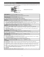
Page 16: ...er values for a time defined using the FINAL SLOPE F12 function 4 Releasing the TORCH TRIGGER will end the welding cycle SPOT WELDING 2T LED switched on SPOT LED switched on This is used so that on pressing the TORCH TRIGGER spot welding is done for a time period set beforehand in seconds after which the arc switches off automatically STITCH WELDING 2T LED switched on SPOT LED flashing To begin st...

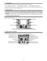
Page 17: ...is reached Push the ENTER MEM Key to open the CONFIG Menu Select the LANGUAGE Sub menu by rotating the ENCODER Knob SX Select the language required by rotating the ENCODER Knob DX Push the MENU Key to close the CONFIG Menu Push the MENU Key to close the SETUP Menu Once this has closed the display will show the various text screens in the language selected Screen saver After a pause or period of in...

Page 18: ...NCES 1011 Fe G3 SI 1 Ø 0 8 Ar 16 20 CO2 MENU Key Provides access to the next menus ENCODER Knob SX Select the welding process ENTER MEM Key This key is used to access PRE SETTING for the process selected continued The following processes are available MIG PULSE MIG DUAL PULSE MIG MAG SYNERGIC MIG MAG MANUAL DIX ARC COOL if activated DIX ARC COOL PIPE if activated DIX ARC HEAVY if activated DIX ARC...

Page 19: ... program ENTER MEM Key Used to access PRE SETTING of the program selected continued WF 793 M CONTROL PANEL It is not possible to access the PROGRAM SELECTION Menu PROGRAM via the WF 793 M control panel 2 WELDING MODE SELECTION Menu MODE PI 3006 M PULS PI 4006 M PULS PI 4606 M PULS CONTROL PANEL To access the WELDING MODE SELECTION Menu MODE push the MENU Key MENU Key ENTER MEM Key ENCODER Knob SX ...

Page 20: ...M Key ENCODER Knob SX ENCODER Knob DX DX Key 1011 Fe G3 SI 1 Ø 0 8 Ar 16 20 CO2 DEFAULT POST GAS 1 0 s MENU Key Used to access subsequent menus if there are any ENCODER Knob SX Used to select the various SPECIAL FUNCTIONS Fx ENTER MEM Key Used to access the PRE SETTING for the program selected beforehand in the MODE chosen and with the changes made to the SPECIAL FUNCTIONS Fx DX Key If held down f...

Page 21: ...Fx LED The operator must press the SPECIAL FUNCTIONS SET UP Fx Key for it to light up and be included in the SPECIAL FUNCTIONS Menu SET UP Fx continued The SPECIAL FUNCTIONS Fx related to the MIG MAG synergic MIG pulsed MIG double pulsed DIX ARC COOL PIPE DIX ARC COOL DIX ARC HEAVY and DIX ARC MEGA FAST processes correspond to the feeder when fitted as follows Table A Special function PARAMETER Di...

Page 22: ...E JOB F28 0 5s 0 1 20 0 s DYNAMICS din 0 30 30 Only for the MIG double pulsed process Only for the DIX ARC MEGA FAST process WARNING The STANDARD or ADVANCED welding CYCLE mode can only be activated by opening the ADVANCED SETUP Menu AD VANCED MODE CYCLE for further explanations see the relevant paragraph This SPECIAL FUNCTION is only to be found if the ADVANCED CRATER function has been activated ...

Page 23: ...NITIAL SLOPE F11 1 0s 0 0 20 0 s FINAL SLOPE F12 1 0s 0 0 20 0 s FINAL WIRE SPEED F13 5 0m min 0 6 MAX m min FINAL VOLTAGE F14 25 0V 10 MAX V FINAL CRATER TIME F15 0 0s 0 0 5 0 s BURN BACK bub 0 30 30 POST GAS PoG 1 0s 0 0 10 0 s FIRST SLOPE I1 TO I2 F18 0 05s 0 00 2 00 s CYCLE WIRE SPEED F19 5 0m min 0 6 MAX m min CYCLE VOLTAGE F20 25 0V 10 MAX V SECOND SLOPE I2 TO I1 F21 0 05s 0 00 2 00 s SLOPE ...

Page 24: ...splay Screen A SPECIAL FUNCTIONS Fx LED SPECIAL FUNCTIONS Fx Key GAS Key ENCODER Knob V PARAMETER SELECTION Key V PARAMETER SELECTION LED V PARAMETER Display Screen V PARAMETER DISPLAY Screen A Shows the value for the parameter indicated by the PARAMETER SELECTION LED A PARAMETER SELECTION LED A The LED unit shows the welding parameter selected using the PARAMETER SELECTION Key A PARAMETER SELECTI...

Page 25: ...UNCTIONS Menu SET UP Fx on the WF 793 M panel and not on the welding power source panel continued 5 WELDING When welding takes place the fields in the displays show the same values as those included for pre setting with the difference that now they are those measured PI 3006 M PULS PI 4006 M PULS PI 4606 M PULS CONTROL PANEL Fe G3 SI 1 Ø 0 8 Ar 16 20 CO2 PROGRAM 1011 A V 217 29 4 WF 793 M CONTROL ...

Page 26: ...s the HOLD box highlighted while on the WF 793 M panel the HOLD Function LED flashes until the end of the HOLD Function If the HOLD Function is Interrupted via a panel it will also be interrupted automatically on the other WF 793 M and vice versa PI 3006 M PULS PI 4006 M PULS PI 4606 M PULS CONTROL PANEL Fe G3 SI 1 Ø 0 8 Ar 16 20 CO2 PROGRAM 1011 A V 217 29 4 HOLD WF 793 M CONTROL PANEL HOLD Funct...

Page 27: ...ton located in the space in which the wire coil is housed NOTE Wire loading cannot be accessed when their are errors on the machine or in the set up procedure WIRE Key 8 DOUBLE FEEDER Two feeders can be connected to the same generator simultaneously Once everything has been configured correctly as indi cated in the WF 793 M operator s manual and set as indicated in the equipment layout section the...

Page 28: ...ble to access the PROGRAM SELECTION Menu PROGRAM via the WF 793 M control panel 2 SPECIAL FUNCTIONS Menu SET UP Fx MMA PI 3006 M PULS PI 4006 M PULS PI 4606 M PULS CONTROL PANEL To access the SPECIAL FUNCTIONS Menu SET UP Fx push the MENU Key MENU Key ENTER MEM Key ENCODER Knob SX ENCODER Knob DX DX Key DEFAULT HOT START 3200 MMA Cr Ni 50 MENU Key Used to access subsequent menus if there are any E...

Page 29: ... the SPECIAL FUNCTIONS Menu SET UP Fx on the WF 793 M panel and not on the welding power source panel SPECIAL FUNCTIONS Fx LED The operator must press the SPECIAL FUNCTIONS SET UP Fx Key for it to light up and be included in the SPECIAL FUNCTIONS Menu SET UP Fx continued The SPECIAL FUNCTIONS Fx related to the MMA process correspond as follows to those on the wire feeder Special function PARAMETER...

Page 30: ...ER Knob V PARAMETER SELECTION Key V PARAMETER SELECTION LED V PARAMETER Display Screen V PARAMETER DISPLAY Screen A Displays the value of the parameter WELDING CURRENT PARAMETER SELECTION LED A The LED unit shows the WELDING CURRENT switched on ENCODER Knob A Adjust the value of the parameter WELDING CURRENT PARAMETER DISPLAY Screen V Shows the parameter indicated by the PARAMETER SELECTION LED V ...

Page 31: ...fields in the displays show the same values as those included for pre setting with the difference that now they are those measured PI 3006 M PULS PI 4006 M PULS PI 4606 M PULS CONTROL PANEL A V 60 70 0 MMA Cr Ni PROGRAM 3200 WF 793 M CONTROL PANEL ...

Page 32: ... DISPLAY shows the HOLD box highlighted while on the WF 793 M panel the HOLD Function LED flashes until the end of the HOLD Function If the HOLD Function is Interrupted via a panel it will also be interrupted automatically on the other WF 793 M and vice versa PI 3006 M PULS PI 4006 M PULS PI 4606 M PULS CONTROL PANEL A V 68 7 2 MMA Cr Ni PROGRAM 3200 HOLD WF 793 M CONTROL PANEL HOLD Function LED ...

Page 33: ...nel to the welding machine 2 Remove the VRD JUMPER on the DIGITAL INTERFACE PCB see figure 3 Use a suitable screwdriver to tighten the 4 screws that fix the control panel to the welding machine 4 Start the welding machine by turning the switch on the rear panel to position I When it switches on but with the machine in stand by the control panel shows that the VRD device is active indication on the...

Page 34: ...ed WF 793 M CONTROL PANEL To access the SPECIAL FUNCTIONS Menu SET UP Fx push the SPECIAL FUNCTIONS Fx Key ENCODER Knob A PARAMETER Display Screen A SPECIAL FUNCTIONS Fx LED SPECIAL FUNCTIONS Fx Key ENCODER Knob V PARAMETER Display Screen V PARAMETER DISPLAY Screen A Displays the selected SPECIAL FUNCTION Fx ENCODER Knob A Used to select the various SPECIAL FUNCTIONS Fx PARAMETER DISPLAY Screen V ...

Page 35: ...welding task begins The HOLD function is not active within the SPECIAL FUNCTIONS Menu SET UP Fx 2 PRE SETTING TIG LIFT PI 3006 M PULS PI 4006 M PULS PI 4606 M PULS CONTROL PANEL MENU Key ENCODER Knob SX A V 111 50 0 MENU Key Used to access the PROCESS SELECTION Menu PROCESS and subsequent menus as applicable ENCODER Knob SX Adjust the value of the parameter WELDING CURRENT continued WF 793 M CONTR...

Page 36: ...e measured voltage PARAMETER SELECTION LED V The LED unit shows the WELDING VOLTAGE switched on continued 3 WELDING TIG LIFT When welding takes place the fields in the displays show the same values as those included for pre setting with the difference that now they are those measured PI 3006 M PULS PI 4006 M PULS PI 4606 M PULS CONTROL PANEL A V 111 50 0 WF 793 M CONTROL PANEL ...

Page 37: ...this phase the DISPLAY shows the HOLD box highlighted while on the WF 793 M panel the HOLD Function LED flashes until the end of the HOLD Function If the HOLD Function is Interrupted via a panel it will also be interrupted automatically on the other WF 793 M and vice versa PI 3006 M PULS PI 4006 M PULS PI 4606 M PULS CONTROL PANEL A V 39 1 2 HOLD WF 793 M CONTROL PANEL HOLD Function LED ...

Page 38: ...2 PROGRAM 0011 002 PRG JOB PROCESS I 001 MMA 97 002 0011 MIG MAG SYNERGIC 211 003 004 005 OVERWRITE JOB 002 To edit and or overwrite a JOB proceed as follows During any welding process and at any time push the MENU Key to exit the welding phase Select the welding process JOB by rotating the ENCODER Knob SX Push the MENU Key to open the JOB table Select the JOB to be edited by rotating the ENCODER ...

Page 39: ...ey Used to access subsequent menus ENCODER Knob SX Used to scroll and select a JOB SEQUENCES ENTER MEM Key Used to select the JOB SEQUENCE displayed continued WF 793 M CONTROL PANEL WELDING MODE SELECTION LED WELDING MODE SELECTION Key WIRE Key ENCODER Knob A PARAMETER SELECTION Key A PARAMETER SELECTION LED A PARAMETER Display Screen A SPECIAL FUNCTIONS Fx LED SPECIAL FUNCTIONS Fx Key GAS Key ENC...

Page 40: ... WARNING All the parameters saved within a JOB including SPECIAL FUNCTIONS Fx can be viewed but not edited PI 3006 M PULS PI 4006 M PULS PI 4606 M PULS CONTROL PANEL MENU Key ENTER MEM Key Display SX Key DX Key m min V 11 1 33 3 013 MENU Key ENTER MEM Key Display SX Key DX Key mm 2 8 0 001 001 Fe G3 SI 1 Ø 0 8 Ar 16 20 CO2 1011 Welding sequence MENU Key Used to access the PROCESS SELECTION Menu PR...

Page 41: ...DE SELECTION LED The LED unit indicates the welding mode saved in the JOB selected which is coherent with the DISPLAY PARAMETER DISPLAY Screen V Displays the JOB number also selected in the SEQUENCES or the value for the parameter indicated by the PARAMETER SELECTION LED V PARAMETER SELECTION LED V The LED unit indicates the welding parameter selected using the PARAMETER SELECTION Key V PARAMETER ...

Page 42: ...ER SELECTION LED A PARAMETER SELECTION LED A The LED unit shows the welding parameter selected using the PARAMETER SELECTION Key A PARAMETER SELECTION Key A Scrolls the active parameters in succession based on the type of welding process saved in the JOB selected In this case where possible the values displayed will be those measured WELDING MODE SELECTION LED The LED unit indicates the welding mo...

Page 43: ...nction LED flashes until the end of the HOLD Function If the HOLD Function is Interrupted via a panel it will also be interrupted automatically on the other WF 793 M and vice versa WARNING All the parameters saved within a JOB including SPECIAL FUNCTIONS Fx can be viewed but not edited PI 3006 M PULS PI 4006 M PULS PI 4606 M PULS CONTROL PANEL m min V 11 1 33 3 013 HOLD mm 2 8 0 001 001 Fe G3 SI 1...

Page 44: ...SE NOTE After resetting has been completed during normal operation of the machine the DISPLAY will still show the er ror signal to inform the operator of the event but this can be removed visually from the display by simply pushing the MENU Key WARNING This only removes the visual error indication but not the history of what happened In the case of NON automatically reset errors to remove the alar...

Page 45: ...witching on the error status presents itself again immediately contact Technical Assistance Department SETUP Menu PI 3006 M PULS PI 4006 M PULS PI 4606 M PULS CONTROL PANEL To access the SETUP Menu hold down for at least 5 consecutive seconds the SX Key SETUP MENU Key ENTER MEM Key ENCODER Knob SX SX Key MENU Key Used to exit the SETUP Menu and take the DISPLAY back to the entry phase ENCODER Knob...

Page 46: ...M Key to confirm and finalise copying of the JOB selected In the case of overwriting confirmation will be requested DELETING THE JOB SELECTED PRG JOB PROCESS I 001 MMA 97 002 0011 MIG MAG SYNERGIC 211 003 MMA 97 004 0011 MIG MAG SYNERGIC 211 005 006 DELETE JOB 004 To delete the JOB selected proceed as follows Select the JOB to be deleted by rotating the ENCODER Knob SX Push the DX Key Push the SX ...

Page 47: ...DUAL PULSE 100A SEQ 001 NAME Sequenza Saldatura Use the DX Key to remove the JOB from the section of the sequence selected using the ENCODER Knob SX Push the ENTER MEM Key to be able to edit the sequence name SEQ NAME JOB 001 Welding sequence 2 002 003 004 005 006 Use the ENCODER Knob DX and the ENCODER Knob SX SX respectively to select the which of the characters available is required and to move...

Page 48: ...splayed Push the SX Key and sequence4 6 will be replaced by sequence 4 whereas the DX Key cancels everything DELETING A SEQUENCE SEQ NAME JOB 001 Welding sequence 2 002 Welding sequence 1 4 003 004 Welding sequence 2 4 005 006 Welding sequence 2 4 Select the sequence to be deleted using the ENCODER Knob SX and push the SX Key SEQ NAME JOB 001 Welding sequence 2 002 Welding sequence 1 4 003 004 Wel...

Page 49: ...on of entering a PASSWORD push the DX Key EDITING THE EXISTING PASSWORD STORE PASSWORD SET PASSWORD 077 WARNING This operation is only possible after having accessed the SETUP Menu using the password you wish to edit To edit the existing PASSWORD proceed as follows Make sure the DISPLAY shows the PASSWORD entered previously a number that must be between 001 and 999 Choose the new PASSWORD to be en...

Page 50: ... any block to be activated on the welding machine but allows the operator to release the machine if its was blocked previously LEVEL 1 BLOCK TYPE LEVEL 1 PARTIAL BLOCK The operator can weld using the parameters set prior to the block and may make adjustments and or changes to the welding parameters using the knobs on the control panels on the welding machine and the wire feeder if fitted LEVEL 2 B...

Page 51: ...DEMAND WIRE LOAD BY GUN DISABLED WIRE LOAD SPEED 8 0 m min If enabled this configuration offers the welder the following additional menus the following icons will be created in the ADVANCED SETUP Menu ADVANCED CONFIG WELD LOG ADVANCED WELDING MODE LANGUAGE ENGLISH ADVANCED CONFIGURATION DISABLED ADVANCED WELDING MODE ENABLED COOLING MODE ON DEMAND WIRE LOAD BY GUN DISABLED WIRE LOAD SPEED 8 0 m mi...

Page 52: ...RESET required from the 5 functions available Function Description RESET PROGRAM RESET PROGRAM 0011 RESET PROCESS DATA MIG MAG SYNERGIC DELETE ALL JOBS COUNTER ALARMS RESET TOTAL RESET EXECUTE PROGRAM RESET Used to return the Special functions Fx of the PROGRAM that the operator is using to their DEFAULT settings only for welding processes for which welding programs are set beforehand NOTE The wel...

Page 53: ...JOBS COUNTER ALARMS RESET TOTAL RESET DATA PROCESS RESET DONE All the functions included in this menu can be used as follows Choose the function e g RESET PROCESS DATA that you intend to use by rotating the ENCODER Knob SX EXECUTE PROCESS DATA RESETTING by pushing the DX Key PROCEED by finalising the reset by pushing the SX Key or cancel the operation by pushing the DX Key To exit the FACTORY RESE...

Page 54: ...s the serial number required for loading special functions at additional cost NETWORK BRIDGE SOFTWARE VERSION WIRE FEEDER SOFTWARE VER 1 WIRE FEEDER SOFTWARE VER 2 ROBOT INTERFACE SW VERS S N NETWORK BRIDGE SOFTWARE VERSION TNI 300415 BETA 0003 DID0 10040204 DID1 106F402E DC0 017F007F This indicates the network interface software version loaded in the board There are also identity codes that are o...

Page 55: ...kage DIX ARC COOL DIX ARC COOL PIPE DIX ARC HEAVY DIX ARC MEGA FAST continua The contents of thus menu are for information only the operator cannot change anything they can only read the information con tained by scrolling the various options available in the menu by rotating the ENCODER Knob SX To exit the INFO Menu and go back to the SETUP Menu Push the MENU Key NETWORK SETUP Menu This menu is u...

Page 56: ...derstand error conditions that have occurred or may be encountered on the welding plant To access the ERROR LOG Menu from the SETUP Menu Turn the ENCODER Knob SX to select the desired icon Push the ENTER MEM Key MENU Key ENTER MEM Key ENCODER Knob SX ENCODER Knob DX Display SX Key DX Key ERRORS Curr Tot E0 5 REMOTE COMMANDS 0 0 E0 6 WATER COOLER MISSING 1 5 E0 7 MOTOR SPEED 0 0 E0 8 WIRE FEEDER MI...

Page 57: ...ENT LAYOUT After this initial check you need to know that this error can only occur in the following cases Water cooler system not connected to the welding machine The welding machine does not recognise the water cooler system even though it is connected correctly Water cooler system disconnected when the machine is operating normally Once the water cooler system has been reactivated this error co...

Page 58: ...ISSING NON automatic reset error Immediately contact technical assistance dept Error visible on DISPLAY ONLY in the event of a fault and NOT in the ERROR LOG Menu Err E1 9 WELDER DEFAULTS MISSING NON automatic reset error Immediately contact technical assistance dept Error visible on DISPLAY ONLY in the event of a fault and NOT in the ERROR LOG Menu Err E2 0 FILE SYSTEM ERROR NON automatic reset e...

Page 59: ...in the ERROR LOG Menu Err E5 4 TIG PROGRAMS MISSING NON automatic reset error Immediately contact technical assistance dept Error visible on DISPLAY ONLY in the event of a fault and NOT in the ERROR LOG Menu Err E5 5 MIG MANUAL PROGRAMS MISSING NON automatic reset error Immediately contact technical assistance dept Error visible on DISPLAY ONLY in the event of a fault and NOT in the ERROR LOG Menu...

Page 60: ...or status presents itself again immediately contact Technical Assis tance Department This is necessary so that our technical assistance dept that must be contacted each time the error messages appear on the welding machine s operator interface is able to resolve the problems more easily and as quickly as possible thanks to the reports by the user and also because in the meantime the welding machin...

Page 61: ...e welding machine to con figure the ENERGY SAVING mode in the best way to allow the best energy saving on the welding plant and to be able to enable an analogue output on the welding plant that can be used for connecting total remote controls equipped with automatic self rec ognition To access the ADVANCED CONFIG Menu from the ADVANCED SETUP Menu Turn the ENCODER Knob SX to select the desired icon...

Page 62: ...on the generator and the feeder being switched off after a set time equal to that for the screen saver which cannot be changed by the operator EXTRA Energy saving is obtained by the screens on the generator and the feeder switching off as soon as the machine is switched on ERROR FILTER TIME ARC ON TIMER 0 gg 0 00 00 TIMER WELDER ON 0 gg 0 13 20 ENERGY SAVING ULTRA ERROR FILTER TIME 300 ms This is ...

Page 63: ...lowing special functions when using the double pulsed MIG welding process DOUBLE PULSED ARC LENGTH F24 Allows the welder to adjust the length of the arc on both double pulsed levels FIRST SLOPE from I1 to I2 see TAB A parameter F22 SECOND SLOPE from I2 to I1 see TAB A parameter F27 These two special functions allow the welder to adjust the ramp for passing between the two double pulsed levels ARC ...

Page 64: ...TE CONTROL 2 RC OPTIONAL TORCH TYPE 2 400A H2O SAFETY CALIBRATION CODE 2 013 OPTIONAL This means that FEEDER 1 2 can or cannot be connected to the welding plant Once feeder 1 2 is detected when the plant is switched on its presence becomes obligatory OBLIGATORY This means that it is obligatory for FEEDER 1 2 to be connected to the welding plant even when the plant is switched on A error condition ...

Page 65: ...ODE 1 CALIBRATION WIRE FEEDER 2 ABSENT REMOTE CONTROL 2 RC OPTIONAL TORCH TYPE 2 400A H2O SAFETY CALIBRATION CODE 2 CALIBRATION By turning ENCODER Knob DX go to CALIBRATION value to read and check instruments values voltmeter and ammeter of the power source NOTE At the end of such operation before restarting welding you should put back the previous value by always turning the ENCODER Knob DX conti...

Page 66: ... via the welding machine s panel ACTIVE In this mode regulation of the ARC LENGTH is active via the robot interface board ROBOT ELECTRONIC INDUCTANCE WATER COOLER OPTIONAL ROBOT CONN MODE RI A 1 ROBOT REG MODE ABS WIRE SP ROBOT VOLTAGE ENABLED ROBOT ELECTRONIC INDUCTANCE DISABLED ROBOT BURN BACK DISABLED ROBOT DYNAMICS DISABLED ROBOT PULSE FREQ DISABLED GAS FLUX CONTROL DISABLED NOT ACTIVE In this...

Page 67: ...ontrol box is ignored ACTIVE In this mode the WIRE PRESENCE input for the MCB 3 motor control box is tested and if necessary the relevant WIRE MISSING alarm is activated via the robot interface board CURRENT MISSING MASK WATER COOLER OPTIONAL ROBOT ELECTRONIC INDUCTANCE DISABLED ROBOT BURN BACK DISABLED ROBOT DYNAMICS DISABLED ROBOT PULSE FREQ DISABLED GAS FLUX CONTROL DISABLED WATER FLUX CONTROL ...

Page 68: ...he settable values are MINIMUM ROBOT ANALOGUE V from 0V to 2V MAXIMUM ROBOT ANALOGUE V from 5V to 14 5V continua To exit the EQUIPMENT LAYOUT Menu and go back to the ADVANCED SETUP Menu Push the MENU Key WELD LOG ADVANCED SETUP Menu The purpose of this menu is to allow the operator to know the latest welding parameters set on the machine as well as the lat est data saved on the machine To access t...

Reviews: