9
•
Partially (depending on the welding process selected) re-
places the ENCODER - V knob on the WF 793.M feeder’s
front panel.
AIR AND/OR WATER COOLED UP/DOWN TORCH
This command (that must be plugged into the relevant connec-
tor on the front panel of the WF 793.M drawing unit) works as
an alternative to:
•
The ENCODER - A knob on the WF 793.M feeder’s front
panel. In “synergic” MIG MAG and “manual” MIG MAG weld-
ing processes, by pressing the two right (+) and left (-) but-
tons you can regulate the values for the synergic welding
parameters.
•
The ENCODER - V knob on the WF 793.M feeder’s front
panel. In the JOB welding process, by pressing the two right
(+) and left (-) buttons you can scroll the welding points set
previously.
The pointing out of any difficulties
and their elimination
The supply line is attributed with the cause of the most com-
mon difficulties. In the case of breakdown, proceed as follows:
1) Check the value of the supply voltage.
2) Check that the power cable is perfectly connected to the
plug and the supply switch.
3) Check that the power fuses are not burned out or loose.
4) Check whether the following are defective:
•
The switch that supplies the welding power source
•
The plug socket in the wall
•
The welding power source switch
NOTE: Given the required technical skills necessary for the
repair of the welding power source, in case of breakdown we
advise you to contact skilled personnel or our technical ser-
vice department.
Replacing the digital interface PCB
Proceed as follows:
•
Unscrew the 4 screws fastening the front rack panel.
•
Remove both the adjustment knobs.
•
Extract wiring connectors from the digital interface PCB.
•
Unscrew the nuts and washers on the support.
•
Remove the digital interface PCB by lifting it out of its sup-
ports.
•
Proceed vice versa to assemble the new digital interface
PCB.
Summary of Contents for DIX PI 3006.M PULS
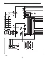
Page 10: ...10 2101EA86 Wiring diagram ...

