background image


  MTG200 Trunk Gateway User Manual


33 


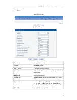
2.9.2 SIP Trunk  

Figure 2-9-2 SIP Trunk 


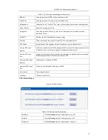
Figure 2-9-3 SIP Trunk Add 


Table 2-9-1 Description of Add SIP Trunk 


Trunk No 


The range of trunk number is 0-1 


Trunk Name 


Description the trunk 


Remote Address 


IP address of remote SIP platform i 


Remote Port 


Q.931  port  of  SIP  of  remote  platform  interfacing  with  this  TG,  the 
default is 5060 


Local Domain 


Refer to SIP parameter 


Get Callee from 


Received the called number from request domain or “To header” 
filed 


Register to Remote 


Defined by IETF work group RFC3372, it is a standard used to 
establish remote communication between SIP and ISUP; the 
default is “Yes”; if SIP trunk does not support, then set it to “No”. 


IP Profile ID 


Refer to IP Group Config->IP Profile-IP Profile ID 


Summary of Contents for MMTG200

Page 1: ...1 MMTG200 Trunk Gateway User Manual V2 0 ...

Page 2: ...MTG200 Trunk Gateway User Manual 2 Revision Records File Name MTG200 Trunk Gateway User Manual Document Version 2 0 Firmware Version 1 2 01 04 03 Date 17 04 2014 Revised by Technical Support Department ...

Page 3: ...RAMETER SETTING 2 1 Login 2 2 Status Statistics 2 2 1 System Information 2 2 2 E1 T1 Status 2 2 3 PSTN Trunk Status 2 2 4 IP Trunk Status 2 2 5 PRI Call Statistics 2 2 6 SIP Call Statistics 2 3 Network 2 4 PRI Config 2 4 1 PRI Parameter 2 4 2 PRI Trunk 2 6 SS7 Config optional 2 6 1 SS7 Trunk 2 6 2 SS7 MTP Link 2 6 3 SS7 Circuit 2 6 4 SS7 Circuit Maintain 2 7 R2 Config optional 2 7 1 R2 Param 2 7 2...

Page 4: ...er 2 9 2 SIP Trunk 2 10 IP Group Config 2 10 1 IP Profile 2 11 Voice Fax 2 12 Maintenance 2 12 1 Management Parameter 2 12 2 Data Restore 2 12 3 Data Restore 2 12 4 Version Information 2 12 5 Firmware Upload 2 12 6 Password Modification 2 12 7 Device Restart 3 GLOSSARY ...

Page 5: ...ll and configure It provides the ability to handle 120 concurrent calls maximum with G711 codec and 64 concurrent calls with G729 Moreover it s support ISDN PRI SS7 and R2 signaling so that provide good connectivity to different PBXs system MTG200 includes following models MMTG201 1E1 single port E1 T1 trunk gateway MMTG202 2E1 two ports E1 T1 trunk gateway MMTG204 4E1 four ports E1 T1 trunk gatew...

Page 6: ...ont View Table 1 2 2 MTG200 Front View Description LED Function Color Work Status POWER Power status indicator Green Off Power is off On Power is on RUN Register indicator Green Slow blinking Unregister Fast blinking Register ALM The failure of device indicator Yellow Off Normal On Failed RST Reset button it is used to restart the device CONSOLE RS232 console port it can be used to debug and confi...

Page 7: ...erface and impedance value is 120Ω Connected end device by cross lines sequence 1 3 Functions and Features 1 3 1 Protocol standard supported Standard SIP PRI protocol Dynamic Host Configuration Protocol DHCP Point to Point Protocol over Ethernet PPPoE Hypertext Transfer Protocol HTTP Domain Name System DNS ITU T G 711A Law U Law G 723 1 G 729AB iLBC optional 1 3 2 System Function Comfort Noise Gen...

Page 8: ...19 Class 1 2 Transportation environment EN 300 019 Class 2 3 Acoustic noise EN 300 753 CE EMC directive 2004 108 EC EN55022 2006 A1 2007 EN61000 3 2 2006 EN61000 3 3 1995 A1 2001 A2 2005 EN55024 1998 A1 2001 A2 2003 CerGficaGons FCC CE 1 3 4 General hardware specification Power supply 12VDC 1A Temperature 0 40 operational 20 70 storage Humidity 10 90 no condensation Max power consumption 15W Dimens...

Page 9: ...ial line Enter the CLI to view or modify the equipment IP Here IP is set to 172 16 33 60 In addition hold down the RST button to restart the device customer can regain the port s default IP Then enter the IP address of device in the browser address bar Customer will see the following page The default user name and password is admin To guarantee the system safety when login for the first time The s...

Page 10: ...teway User Manual 10 2 2 Status Statistics Users through to traverse the left navigation tree and can complete view edit and configuration device in the right configuration interface TG configuration flow chart below ...

Page 11: ...gateway Management Ethernet Interface Include IP address subnet mask of FE1 DNS DNS server IP address System Up Time Time elapsed from device power on to now Traffic Statics Total bytes of message received and sent by FE0 port Equipment Type Equipment type this equipment is MTG200 Hardware Version Hardware version of device DSP Version Digital signal processing chip driver version Web Version Vers...

Page 12: ...t and the AIS defect still exists after the Loss of frame failure which is caused by the unframed nature of the all ones signal is declared The AIS failure is cleared when the Loss Of Frame failure is cleared 4 Disable Means that this E1 T1 is not used 5 ISDN SS7 Signal Alarm Means physical connection is normal signaling link has problem 6 Active OK Means that physical connection and signaling lin...

Page 13: ...responds to a PRI link Trunk Name Used to identify the name of the trunk E1 T1Port No Indicate the E1 T1 line occupied by the PRI trunk Link Status Indicate whether the PRI link is established 2 2 4 IP Trunk Status Figure 2 2 4 IP Trunk Status Table 2 2 4 Description of IP Trunk Status SIP Trunk No The number of SIP trunk Username When SIP trunk is under registered mode change the value in the con...

Page 14: ...ame The name used to describe the PRI trunk Current Calls Number of lines that are being called currently Accumulated Calls Total number of calls from running start of system to current time ASR The percent of calls completed in total calls This statistics page show the reasons for release of the call including Normal Call Clearing Call Rejected User Busy No User Response No Circuit Available Unas...

Page 15: ... trunk Trunk Name The name used to describe the PRI trunk Current Calls Number of lines that are being called currently 2 3 Network Figure 2 3 1 Network Configuration Table 2 3 1 Description of Network Configuration Service Ethernet Obtain IP address automatically If Selected the TG will obtain IP address via DHCP ...

Page 16: ...eed fill Primary DNS server addresses the secondary DNS Server is optional Ntoe FE0 port IP and FE1 port IP should be set in different segments After configure the network address and restart the gateway configuration to take effect 2 4 PRI Config 2 4 1 PRI Parameter Figure 2 4 1 PRI Parameter Table 2 4 1 Description of PRI Parameter Calling Party Numbering Plan Provide six plans Unknown ISDN Tele...

Page 17: ...vide six plans Unknown ISDN Telephony numbering plan data numbering plan telegraph numbering plan national standard numbering plan private numbering plan The default is ISDN Telephony numbering plan Called Party Number Type Six optional types are provided for called party Unknown International number National number Network special number User number Short code dialing The default option is Unknow...

Page 18: ...e whether E1 T1 supports D channel the default is Yes E1 T1 Port No E1 T1 port number is numbered according to the physical position of E1 T1 it generally starts from 0 Protocol Interface type of PRI There are two types are available ISDN and QSIG the default is ISDN Switch Side Indicate PRI network property of E1 T1 it is divided into User side and Network side When PRI loopback is carried out th...

Page 19: ...is 24bits and Hex are selected the structure is like xyz and x y z must be hex number between 00 FF eg 33AA55 6 When SPC length is 14bits and ITU Pointcode Structure are selected the structure is like x y z and x z must be decimal number between 0 7 and y must be decimal number between 0 255 eg 6 222 3 7 When SPC length is 14bits and Hex are selected the structure is like xyz and x z is a 3 bit he...

Page 20: ...ll be selected according to physical circumstances Note 1 If protocol standard chose ANSI or ITU CHINA and then the SPC length is 24 bits 2 If protocol standard chose ITU and then the SPC length is 14 bits 3 SPC length performance on the OPC DPC structure SPC pattern instructions of the different structure OPC DPC input formats 4 When the SPC length is 24 bits and chosen ITU OPC DPC structure form...

Page 21: ...om failure and then they will share the load again Signaling Link Code If a signaling point has established several signaling links then the code of each signaling link will begin from 0 E1 T1 Port No Indicate which E1 T1 this link is established on it is stipulated that such numbering is carried out according to the physical position of E1 T1 Channel No Indicate time slot that link is established...

Page 22: ...tion SS7 Circuit Add Trunk No The Trunk No here corresponds to the Trunk No of SS7 trunk E1 T1 port No Fill in the port number of E1 T1 Assign E1 T1 to selected SS7 trunk Start Channel The start of SS7 channel trunk Start CIC No An initial circuit number to this E1 T1 matches by both parties Count A total of 32 channels 2 6 4 SS7 Circuit Maintain According to the different operating modes 7 circui...

Page 23: ...ional Port No Display the port number Protocol Type TUP or ISUP Status There are 16 status with ports each state corresponds to a color activated disable fault RAI Alarm ISDN SS7 Signal Alarm Frame Sync Idle Signal Busy L blocked R blocked B blocked Blocking Unblocking and Resetting These ports can work in many ways Select All Invert Clear Block Unblock Reset and Cancel ...

Page 24: ...hannel If user wants to manage the channel please select operation mode to channel Select current port use will see port status and protocol type The following will show the slot and channel status There are 16 kinds of channel states and each state corresponds to a color ...

Page 25: ...ig optional 2 7 1 R2 Param Figure 2 7 1 R2 Parameter It is the default configuration for MTG200 Description says the state name means the different countries supported R2 parameters standards According to demands add R2 parameters of user countries ...

Page 26: ...MTG200 Trunk Gateway User Manual 26 Figure 2 7 2 R2 Parameter Add ...

Page 27: ...ed and each other can send a next number Request category Means KA request code of R2 lines signaling DNIS end flag The front party notices the rear party that the called numbers send completely ANI end flag The front party notices the rear party that the callee numbers send completely Address Complete The rear party notices the front party that the called and the callee numbers received completel...

Page 28: ...arameters Figure 2 8 2 E1 T1 Parameter Table 2 8 1 Description of Modify E1 T1 Parameter Work Mode E1 or T1 the default is E1 PCM Mode PCM mode A LAW and Mu LAW the default is A LAW Frame Mode The frame modes of E1 T1 are DF CRC 4 CRC4_ITU the default is CRC 4 the frame modes of T1 are F12 F4 ESF F72 the default is F4 Line Code Line codes of E1 T1 are NRZ CMI AMI HDB3 the default is HDB3 The line ...

Page 29: ...t equipment supports in the grouping will be displayed in 0 group Default value cannot be modified Coder Support 3 kinds of voice codec G 711A U G 729 G 723 Payload Type Value Each codec has a unique value refer to RFC3551 Packetization Time ms Voice Codec packetization time user can define different kinds of coding and decoding minimum packetization time Rate kbps Show the voice data flow rate Si...

Page 30: ...r to identify a dial plan Index Dial plan priority rules take effect in accordance with dial plan index size and not according to the maximum number received Prefix Match number representative of any number Min Length The minimum receiving Number length 0 to 30 If receiving a number equal to the minimum length greater than less than equal to the maximum length the number will be used to continue t...

Page 31: ...x number Time to Reach Min Length after Prefix After receiving prefix number the number has not yet reached the length of the minimum receiving number the length of timeout Time to Reach Max Length after Min Length After receiving number the number has reached the minimum length but not reached the maximum length of the dial timeout 2 8 5 PSTN Profile PSTN profile is used to configure PSTN call nu...

Page 32: ...three ways to send DTMF RFC2833 SIP INFO INBAND in accordance with the priority choice to send the configuration mode Overlap Receiving Not enabled by default only enable this feature Dial plan and Dial timeout have the meaning Remove CLI Default does not remove CLI Play busy tone to PSTN Equipment will play busy tone from IP to PSTN 2 9 SIP Config 2 9 1 SIP Parameter Figure 2 9 1 SIP Parameter SI...

Page 33: ...emote Port Q 931 port of SIP of remote platform interfacing with this TG the default is 5060 Local Domain Refer to SIP parameter Get Callee from Received the called number from request domain or To header filed Register to Remote Defined by IETF work group RFC3372 it is a standard used to establish remote communication between SIP and ISUP the default is Yes if SIP trunk does not support then set ...

Page 34: ... If Yes is selected then input limitation number of calls in the edit box appeared IP to PSTN Time Restriction The default setting is disabled If Enabled is selected then user can edit the start and stop time of prohibition time interval Within this time interval all calls from IP to PSTN are prohibited Calls from PSTN to IP are not limited Detect Trunk Status Detect the status of SIP trunk If sel...

Page 35: ... to local it will play from the equipment and set to IP it will play by the called Ringback Tone to IP originated from PSTN IP call ring back tone player side if set to local it will play from the equipment and set to PSTN it will play by the called Wait for RTP Packet from Peer If set to No will auto send RTP packets during the call if set to Yes will wait the RTP packet was sent by the opposite ...

Page 36: ...call s silence time longer than silence timeout that for a long time not received RTP packets then hangup the call Period without RTP packet The maximum time length of silence PSTN in Gain Incoming PSNT gain IP in Gain Incoming IP gain Timeout of no answer Call from PSTN Call timeout of no answer from PSTN Call from IP Call timeout of no answer from IP ...

Page 37: ...ndant frame in packet The length of frame in RTP packet Data Fax Control Data Whether to allow the control of voice data Fax Whether to allow the control of fax DTMF Parameter Continuous time The level of a frequency duration Signal interval The time interval between two different frequency signals Threshold for detection Frequency detection threshold 2 12 Maintenance 2 12 1 Management Parameter F...

Page 38: ...ocol is enabled or not the default is Yes Primary NTP server Address The Primary IP address of SNMP management host computer The host computer of the IP address will carry out monitoring and management to equipment Primary NTP server Port The port that managed device provides trap message it is generally alarm message to SNMP management host computer the default is 123 Secondary NTP server Address...

Page 39: ...e 2 12 4 Version Information Figure 2 12 4 Version Information Here users can view software database and web version information 2 12 5 Firmware Upload Figure 2 12 5 Firmware Upload The process of firmware upload 1 Click Firmware Upload 2 Browse files and choose the loading program Name the file extension ldf 3 Click Upload the upload process will last about 60s and device can automatically restar...

Page 40: ...2 9 7 Device Restart Some configuration need to restart device to take effect Click Restart to restart the device 3 Glossary PRI Primary rate interface FMC Fixed Mobile Convergence SIP Session Initiation Protocol DTMF Dual Tone Multi Frequency PSTN Public Switched Telephone Network STUN Simple Traversal of UDP over NAT DMZ Demilitarized Zone SS7 Signaling System No 7 ISDN Integrated Services for D...

Page 41: ...rentiated Services Code Point OPC Original Signaling Point Code DPC Destination Signaling Point Code NGN Next Generation Network PBX Private Branch Exchange RTP Real time Transport Protocol RTCP Real time Transport Control Protocol STP Signaling Transfer Point TDM Time Division Multiplex ...

Reviews: