background image


UC2000 User Manual 

      23 

Copyright @ 2011-2015 Dinstar 


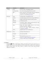
Filesystem 

The current utilization rate of the file system 

Memory   

The current utilization rate of the memory 

Mac Address 

The  Mac  address  of  the  network  port,  which  is  used  for  network 

communication 

Type 

The type of IP address, which can be Static IP, PPPoE or DHCP 

IP Address 

The IP address of the network port   

Netmask 

The netmask of the network port 

Gateway 

The gateway address of the network port 

DNS 

The DNS address of the network port 

RX/TX (Per Second) 

The  bit  rate  of  receiving  and  sending  messages  per  second  over  the  network 

port   

RX/TX (Total) 

The total amount of messages received and sent over the network port since the 

device is booted up 

Expires 

The time remaining until expiry for DHCP IP address   

Connected 

The running time of the network port since the device is booted up 


4.3.2


SIP 

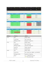
Click 

Status 

  SIP

, and the following  interface will be displayed. On the interface, information of SIP 

profile, SIP Trunk and SIP extension is shown. 


Summary of Contents for UC2000

Page 1: ...es Co Ltd Address 9th Floor Guoxing Building Changxing Road Nanshan District Shenzhen China Postal Code 518052 Telephone 86 755 61919966 Fax 86 755 2645 6659 Emails sales dinstar com support dinstar c...

Page 2: ...Revision Records Document Name UC2000 User Manual v1 0 Document version V1 0 Firmware version 2 50 1 2 Revised by Ivanka Yuan Date 2014 6 3 Changes Draft...

Page 3: ...vironment 6 2 Quick Installation 7 2 1 Attentions for Installation 7 2 2 Installation Procedures 7 2 2 1 Installation of Userboard and Master Control Board 7 2 2 2 How to insert SIM Card 9 2 2 3 Insta...

Page 4: ...Other SIP Clients registered to UC2000 20 4 2 4 UC2000 Connected to PBX through Trunking 21 4 3 Status 21 4 3 1 Overview 21 4 3 2 SIP 23 4 3 3 PSTN 24 4 3 4 Current Call 26 4 3 5 CDRs 26 4 3 6 Service...

Page 5: ...ension 48 4 7 1 SIP Extension 48 4 7 2 FXS 49 4 7 3 Ring Group 50 4 8 Trunk 51 4 8 1 SIP Trunk 51 4 8 2 FXO Trunk 53 4 8 3 GSM CDMA Trunk 55 4 9 Call Control 55 4 9 1 Setting 56 4 9 2 Route Group 57 4...

Page 6: ...a single communication way such as traditional PBX to a comprehensive communication way which integrates VoIP PLMN and PSTN It also provides a united communication GUI for PLMN based or PSTN based vo...

Page 7: ...UC2000 User Manual 2 Copyright 2011 2015 Dinstar 1 3 Product Appearance 1 3 1 Image of UC2000 1 3 2 Description of Ports and Indicators...

Page 8: ...re GSM SIM card is inserted 8 SIM Card Indicator Flash slowly SIM card has been inserted and usable On dull SIM card is not inserted or SIM card is unavailable 9 Slot for CDMA SIM Card Slot where CDMA...

Page 9: ...al plan via time numbers source IP etc Simple and easy deployment integrate seamlessly with your current system CDRs on local SMS sending and receiving User friendly web interface multiple management...

Page 10: ...ine 1 4 5 Physical Interfaces 12 Expansion Slots Expansion Boards 2 FXS Ports per Board 2 FXO Ports per Board 1 GSM Channel per Board 1 CDMA Channel per Board 1 WCDMA Channel per Board 1 BRI Port per...

Page 11: ...8V 3 0V Antenna Panel Mount or External Cable 3 0dB SMA Connector SMS USSD Bulk SMS SMS Code Decode ASCII Unicode IMEI PIN Code Management 1 4 8 Hardware Specifications Environment Power Supply 100 24...

Page 12: ...e sure the antenna of UC2000 is well connected If you want UC2000 to communicate with the GSM network or the CDMA network please insert an SIM card Note Please check whether power supply is up to the...

Page 13: ...of Master Control Board Installation of Master Control Board Please insert the master control board into the slot on the back panel of UC2000 Ensure that the master control board matches well with th...

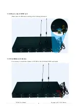
Page 14: ...ght 2011 2015 Dinstar 2 2 2 How to insert SIM Card Please insert the SIM card according to the following indication 2 2 3 Installation of Antenna It is necessary to install the antenna on UC2000 for t...

Page 15: ...t interfaces namely FE0 and FE1 UC2000 Switch PC FE0 192 168 11 1 192 168 11 10 Note The IP address of FE0 port and the IP address of PC should be at the same network segment As for the basic configur...

Page 16: ...oming call while keeping the current call holding on by pressing the flash button or the flash hook When the called party presses the flash button or the flash hook once again he or she will switch ba...

Page 17: ...ersation and B wants to consultatively transfer the conversation to C the extension of C is 8000 Operation instructions are as follows 1 B dials 28000 2 is the feature code for attended transfer 8000...

Page 18: ...o extension number 8000 73 Disable unconditional call forwarding service 90 Enable the call forwarding on busy service Example Dial 90 8000 and calls will be forwarded to extension number 8000 when th...

Page 19: ...ass through 3 6 2 Explanation of T 38 and Pass through T 38 T 38 is used to transfer faxes over IP networks in real time It could convert the analog fax signal into digital fax signal and could transf...

Page 20: ...e selected parts will be restored to defaults 3 9 Local Maintenance To ensure easy maintenance the UC2000 gateway provides a standard RS232 console port which has a Baud rate of 115200bps Users can lo...

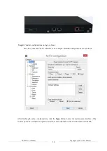
Page 21: ...tware Herein we take the PuTTY sofeware as an example Detailed configurations are as follows After finishing the above configurations click the Open button to enter the maintenance interface of the co...

Page 22: ...P address of UC2000 needs to be configured as 172 30 66 100 and netmask is 255 255 0 0 enable enable configure config interface ethernet config if br lan ip address 172 30 66 100 255 255 0 0 config if...

Page 23: ...nt with the IP address of UC2000 device since the default IP address of the UC2000 device is 192 168 11 1 Check the connectivity between the PC and the UC2000 Click Start Run of PC and enter cmd to ex...

Page 24: ...cations should be saved Click the button and you can see a log of all changes Those changes won t take effect until they are saved 4 Auto Refresh Button The button can be enabled or disabled If it is...

Page 25: ...port calls through the port will take inbound and outbound routes as first priority For outgoing calls if outbound route cannot be matched then the registered SIP trunk will be selected For incoming...

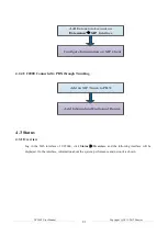
Page 26: ...SIP Client 4 2 4 UC2000 Connected to PBX through Trunking Add an SIP Trunk to PBX Add Inbound and Outbound Routes 4 3 Status 4 3 1 Overview Log in the Web interface of UC2000 click Status Overview an...

Page 27: ...ting interface Device SN The SN of the device Hardware ID The hardware ID of the device which cannot be modified Firmware Version The version number of the firmware and the time when the firmware is c...

Page 28: ...port Gateway The gateway address of the network port DNS The DNS address of the network port RX TX Per Second The bit rate of receiving and sending messages per second over the network port RX TX Tot...

Page 29: ...ge will be sent to peer device the peer device is reachable Status Green color means available while red color means abnormal unavailable or prohibited There are five statuses Running Reged Up Noreg U...

Page 30: ...tus Registered Unregistered FXO State Ready Unready Config Status OK Config Failed SIP Register Status Registered Unregistered Hook State Onhook Offhook Line State Online Offline GSM State Ready Unrea...

Page 31: ...ll State There are three states Active it means the caller and the called party is on conversation Ringing it means the phone of the called party is ringing Early It means the ring back tone of the cu...

Page 32: ...be disabled and their ports can be modified on the System Access Control interface If no running status is shown it means exception has occurred on the UC2000 Besides if syslog is disabled on the Syst...

Page 33: ...r 4 4 System Configurations for language time zone NTP login password access control provision operation log service log upgrade backup restore automatch impedance IVR upload and device reboot can be...

Page 34: ...Log Level There are eight levels including Debug Info Notify Warning Error Critical Alert and Emergency Enable built in NTP server If built in NTP server is enabled the UC2000 can be synchronized with...

Page 35: ...box on the right of Enable and you will see the following interface Parameter Explanation URL The URL of the http ftp tftp server for example ftp 172 16 77 200 home tftp 172 16 77 200 provision xml ht...

Page 36: ...the Export button at the top right corner 4 4 5 Service Log Service logs the running logs of UC2000 can be exported on the System Service Log interface Those logs are used for analyzing where a probl...

Page 37: ...ed to improve the interoperability of the FXO userboards with other devices How to use automatch impedance 1 Select the to be matched FXO port in the drop down box 2 Connect a telephone cable to the F...

Page 38: ...fter the device is rebooted those configurations that have been saved will remain unchanged 4 5 Network UC2000 only works in bridge mode with FE0 port and FE1 port functioning identically 4 5 1 Settin...

Page 39: ...mic IP address which is assigned ad hoc at the start of each session normally changing from one session to the next If you choose static IP address you need to fill in the following information IPv4 A...

Page 40: ...address refers to IP address assigned through the PPPoE protocol If you choose PPPoE you need to fill in to fill in the following information Username the account name of PPPoE Password the password...

Page 41: ...ing and then click Ping 2 If related messages are received it means the network works normally otherwise the network is not connected or is connected faultily Traceroute is used to determine a route f...

Page 42: ...o set source IP source port destination IP or destination port to capture the packages that you want Note If there are multiple IP addresses please use to separate them 4 6 Profile 4 6 1 SIP Profile O...

Page 43: ...ds for NAT traversal including static NAT IP Address and Host dynamic NAT uPNP NAT PMP and STUN NAT can also be disabled off DTMF Type There are three modes including SIP Info INBAND RFC2833 RFC2833 P...

Page 44: ...mode Inbound Codec Profile The inbound codec profile supported by SIP of UC2000 Make reference to Profile Codec Outbound Codec Profile The outbound codec profile supported by SIP of UC2000 Make refer...

Page 45: ...executed the press on flash hook won t be processed DTMF Send Interval ms The minimum interval between the sending of two DTMF tone DTMF Dual Tone Multi Frequency DTMF Gain Signal gain of DTMF DTMF D...

Page 46: ...Timeout s The timeout value for dialing a digit of a telephone number the default is 4 seconds Dial Timeout s The timeout value for dialing the first telephone number after off hook the default is 10...

Page 47: ...f a DTMF tone Detect Caller ID Whether to detect caller ID default value is On Ring Detection Detect caller ID after ringing or detect caller ID before ringing Dialplan The rules for dialing 4 6 3 Cod...

Page 48: ...tion Name The name of the number profile Prefix of Caller Number The prefix of the calling number It supports regular expression Prefix of Called Number The prefix of the called number It supports reg...

Page 49: ...route Click the New button and you will see the following interface Parameter Explanation Name The name of the time profile Date Period Choose a start date and an end date Add a date period Delete a...

Page 50: ...mber or the calling number Delete Suffix The number of digits that are deleted from the right of the caller number or the calling number Add Prefix The prefix added to the caller number or the calling...

Page 51: ...nvalid 4 6 7 Dialplan Dialplan is used for number dialing of calls through FXS and FXO ports Regex Regular Expression Syntax Explanation of frequently used metacharacters in Regex Matches the starting...

Page 52: ...hes the phone numbers with the first digit as 1 the second digit as 3 5 or 8 the left nine digits as any of 0 to 9 Digit Map Syntax Supported objects Digit 0 9 T Timer DTMF A digit a timer or one of t...

Page 53: ...on and you will see the following interface Parameter Explanation Name The name of the SIP extension Extension The SIP account of the extension registered in UC2000 by a SIP client Password The passwo...

Page 54: ...address is allowed to register the SIP account of this extension SIP Profile The SIP profile that is selected for the extension Status If it is enabled the SIP account can be registered Otherwise the...

Page 55: ...extension rather than choosing a route Input Gain The receiving gain of the FXS port Output Gain The sending gain of the FXS port FXS Profile The FXS profile that is selected for the FXS extension mak...

Page 56: ...erface first Add an extension Delete an extension Strategy The strategies for choosing which SIP extension to ring including Sequence Ascending Sequence Cyclic Ascending Simultaneous and Random Ring G...

Page 57: ...utbound proxy is used enter the IP address or domain name of the proxy server Port If outbound proxy is used enter the listening port of the proxy server Transport Transport protocol TCP or UDP Regist...

Page 58: ...r the SIP trunk If all ports of UC2000 intend to register to a server you need to configure a SIP trunk connecting UC2000 and the server then enable register for the ports and designate the SIP trunk...

Page 59: ...be in use when it is successfully registered but the master server fails to be registered Auth Username the auth username of the SIP server it is optional to fill in Password the password of the SIP...

Page 60: ...he GSM CDMA port which is used to register Status If it is enabled it means the GSM CDMA trunk is available otherwise the GSM CDMA trunk is unavailable Autodial Number The autodial number for incoming...

Page 61: ...rt The start port of RTP packets RTP End Port The end port of RTP packets Local extension call If it is enabled calls between local extensions do not need routes Fax Mode T38 or T30 Pass through Tone...

Page 62: ...hich trunk as the destination route under a route group Click and you will see the following interface Parameter Explanation Name The name of the route group Members Select Select extension s or trunk...

Page 63: ...rity Name The name of the route Condition The condition under which the route will be used Source The source of the call it can be an extension a trunk a customized source or any source Number Profile...

Page 64: ...e manipulated make reference to Profile Manipulation Destination The destination of the route Failover Action The processing action when a call through this route fails Condition If busy or timeout is...

Page 65: ...ght 2011 2015 Dinstar 4 9 4 Feature Code Note All feature codes are enabled by default 4 9 5 IVR On the IVR interface you can carry out specific configurations for the IVR which has been uploaded from...

Page 66: ...TMF tone is received during 10 seconds the IVR will be played repeatedly or the call will be hanged up The default value is 20 seconds Enable Direct Extension Whether to allow direct dialing of extens...

Page 67: ...le recipients use to separate them for example 13151103146 18954405566 Receive Message All SMS received by UC2000 are displayed on the Receive List Read Message Click on the Receive List to read SMS c...

Reviews: