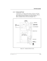
The component panel has two slide releases to lock it in a
fully closed (in) or open (out) position. Press the slide release
at the upper horizontal edge of the panel to release the detent.
The panel will lock at about three quarters of its total travel
when you pull it out. This prevents it from being pulled
entirely out of the tracks and possibly damaging the
components. To reinsert the panel, press the second slide
release and push it back into its closed position. The fully
closed position locks the panel and prevents it from being
forced outward by pressure from the various tubing
arrangements.
The panel can be pulled completely out by pressing the
second slide release and pulling the panel until it clears the
top and bottom tracks. Hold the panel securely when it
disengages the tracks. To replace the panel, align it with the
top and bottom tracks and push inward until it engages the
second detent. Press the second slide release and push the
panel to its closed and locked position.
Various component arrangements are made possible by
multiple mounting holes and slots. The configuration shown
here is only one of many offered by the enclosure.
2.3.2 Rheodyne Injection Valve
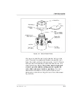
The Rheodyne injection valve is mounted at the bottom of the
component panel. Its control knob extends through the door
to allow manual operation with the door closed. The valve
has two operating positions:
INJECT
and
LOAD
.
The injection valve is a low-volume, metal-free, 35 MPa
(5000 psi) rotary injection valve. It accommodates syringe
injections or pressurized sample loading.
The Rheodyne injection valve is equipped with a microswitch
for detection of the valve position. The microswitch can be
wired to a module that can process the signal to verify the
position of the valve.
LC20 Chromatography Enclosure
2-6
Doc. 034859-02 9/93
Summary of Contents for LC20
Page 6: ...Contents iv Doc 034859 02 9 93 ...
Page 8: ...LC20 Chromatography Enclosure 1 2 Doc 034859 02 9 93 ...
Page 12: ...LC20 Chromatography Enclosure 2 2 Doc 034859 02 9 93 ...
Page 24: ...LC20 Chromatography Enclosure 2 14 Doc 034859 02 9 93 ...
Page 26: ...LC20 Chromatography Enclosure 3 2 Doc 034859 02 9 93 ...
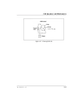
Page 29: ...Figure 3 7 Drawing Sample 3 Operation and Maintenance Doc 034859 02 9 93 3 5 ...
Page 32: ...LC20 Chromatography Enclosure 3 8 Doc 034859 02 9 93 ...
Page 34: ...LC20 Chromatography Enclosure 4 2 Doc 034859 02 9 93 ...
Page 40: ...LC20 Chromatography Enclosure 4 8 Doc 034859 02 9 93 ...
Page 42: ...LC20 Chromatography Enclosure 5 2 Doc 034859 02 9 93 ...
Page 50: ...LC20 Chromatography Enclosure 5 10 Doc 034859 02 9 93 ...
Page 52: ...LC20 Chromatography Enclosure A 2 Doc 034859 02 9 93 ...
Page 56: ...LC20 Chromatography Enclosure B 2 Doc 034859 02 9 93 ...
Page 65: ...Figure B 6 Electrochemical Cell Plumbing Schematic B Installation Doc 034859 02 9 93 B 11 ...


