3
•
Operation and Maintenance
3.1 Routine Operation
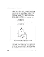
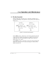
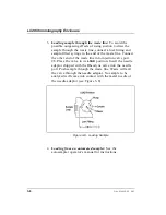
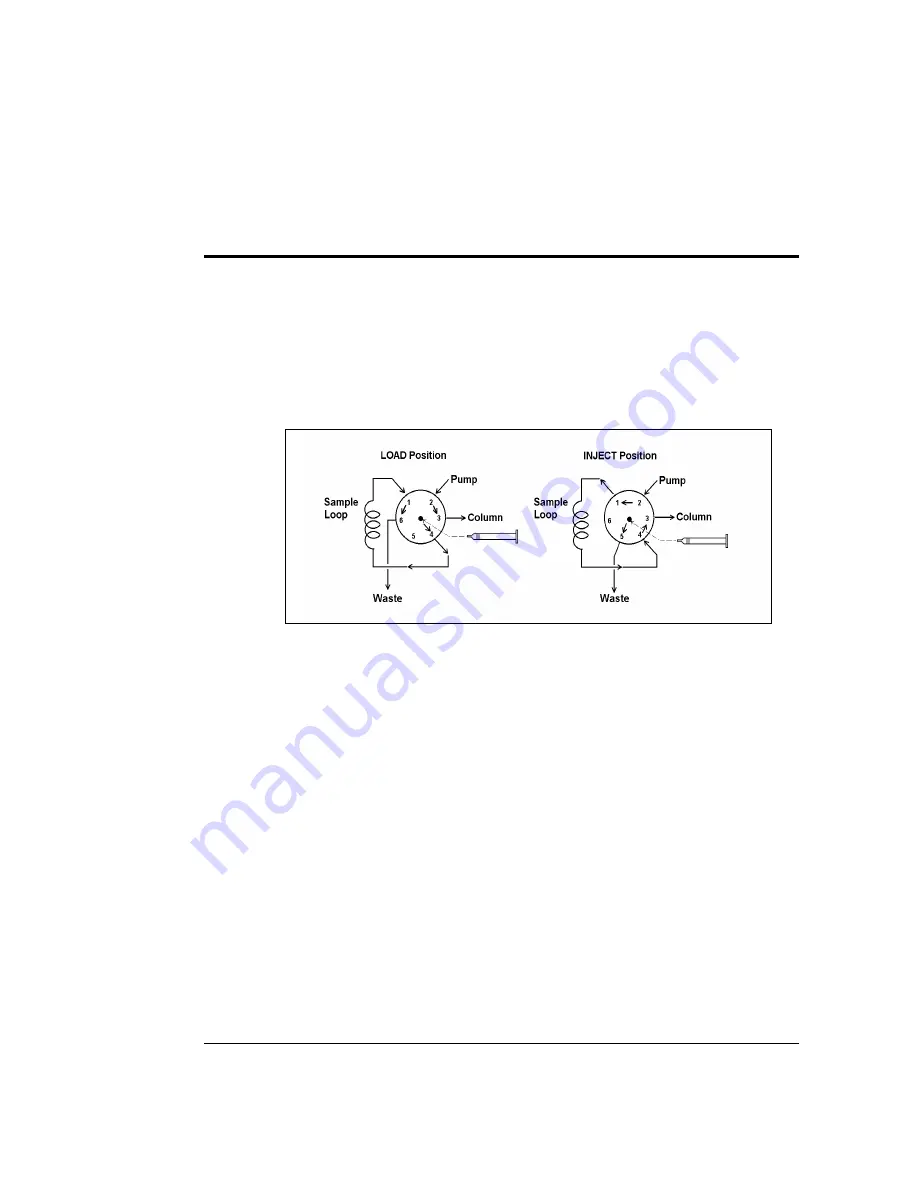
Inside the Rheodyne injection valve, eluent flows through one of
two paths depending on the position of the injection valve knob (see
Figure 3-6).
In the
LOAD
position, eluent flows in from the pump and out to the
column without entering the sample loop. Sample flows from the
syringe into the valve and through the sample loop, and excess
sample flows out to waste.
In the
INJECT
position, eluent flows in from the pump, through the
sample loop, and out to the column (carrying the contents of the
sample loop with it).
Figure 3-6. Injection Valve Schematic
Doc. 034859-02 9/93
3-3
Summary of Contents for LC20
Page 6: ...Contents iv Doc 034859 02 9 93 ...
Page 8: ...LC20 Chromatography Enclosure 1 2 Doc 034859 02 9 93 ...
Page 12: ...LC20 Chromatography Enclosure 2 2 Doc 034859 02 9 93 ...
Page 24: ...LC20 Chromatography Enclosure 2 14 Doc 034859 02 9 93 ...
Page 26: ...LC20 Chromatography Enclosure 3 2 Doc 034859 02 9 93 ...
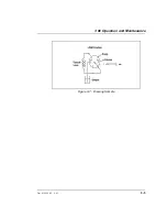
Page 29: ...Figure 3 7 Drawing Sample 3 Operation and Maintenance Doc 034859 02 9 93 3 5 ...
Page 32: ...LC20 Chromatography Enclosure 3 8 Doc 034859 02 9 93 ...
Page 34: ...LC20 Chromatography Enclosure 4 2 Doc 034859 02 9 93 ...
Page 40: ...LC20 Chromatography Enclosure 4 8 Doc 034859 02 9 93 ...
Page 42: ...LC20 Chromatography Enclosure 5 2 Doc 034859 02 9 93 ...
Page 50: ...LC20 Chromatography Enclosure 5 10 Doc 034859 02 9 93 ...
Page 52: ...LC20 Chromatography Enclosure A 2 Doc 034859 02 9 93 ...
Page 56: ...LC20 Chromatography Enclosure B 2 Doc 034859 02 9 93 ...
Page 65: ...Figure B 6 Electrochemical Cell Plumbing Schematic B Installation Doc 034859 02 9 93 B 11 ...

