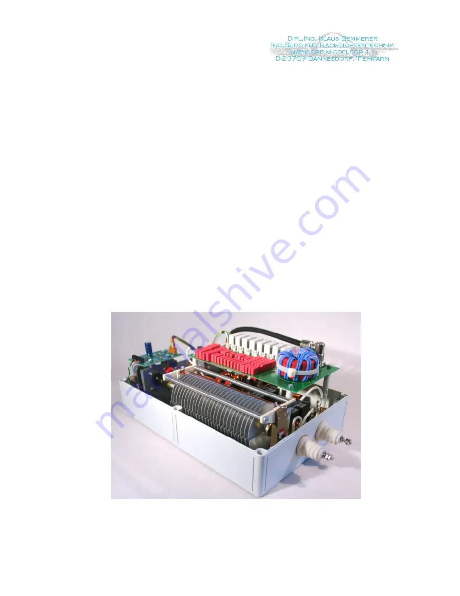
RF Unit:
The RF Unit is contained in a weather-protected cabinet (IP66) and is UV resistant. There
are two feed-thru insulators to connect to the antenna elements. The coaxial cable and the
control cable are connected via a N and a 25 pin connectors. There is no active circuitry
inside the RF Unit. This is to insure reliable operation even under non-matched condition.
The LC network is known as Balanced PI. At the front end of the network there is a balun
transformer that matches the unsymmetrical coax cable to the symmetrical tuner elements.
This is the only place where the impedance of the system is purely resistive (when
matched) and is the ideal place for the Balun. The regular station SWR meter (or the built-
in meter in the TRX) is used as an indicator to match the antenna.
The capacitors at front end are switched in 256 steps of 17 pF per step. The capacitor at
antenna side is a variable capacitor of 400 pF. The control of this capacitor is by a stepper
motor with 0.9° per step. The inductive paths between the capacitors are switched in 31
steps from 0.2 µH to 35 µH. Switching is done by power relays. With the circuit
components used it is possible to match short antennas up to an unlimited antenna length
within the RF range from 1.8 to 30 MHz.
.
Interior view of the RF unit looking at the capacitor board, the inductor board is located below
Page 5 of 24


