1 3
D I R E C T H E A L T H C A R E S E R V I C E S . C O . U K
S E R V I C E M A N U A L
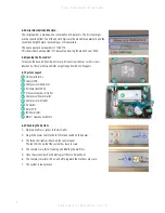
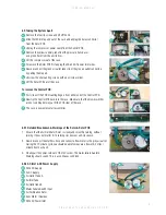
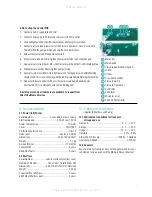
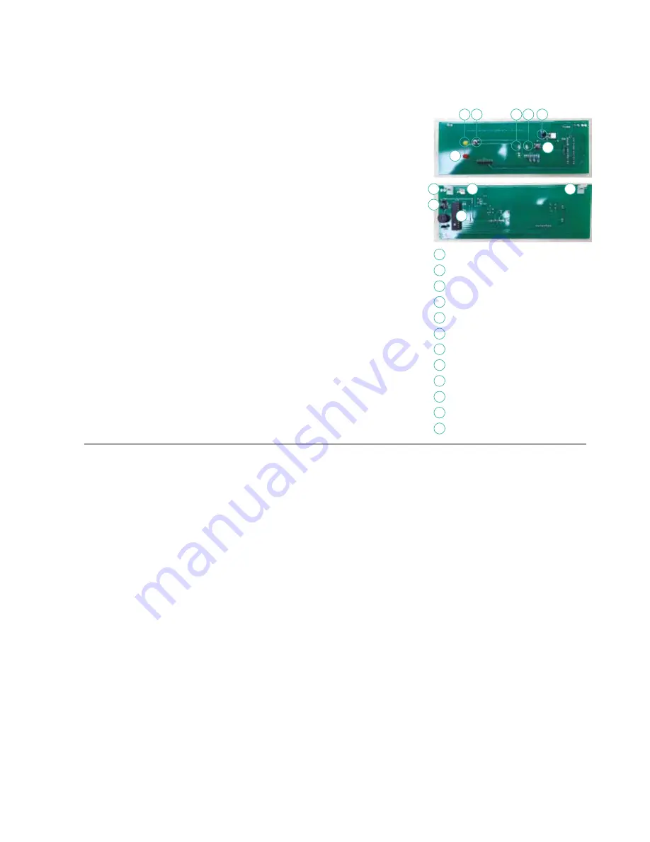
8.9.6 Testing the Control PCB
1. Connect a 5v DC supply to the DC inlet.
2. Connect 240v supply to AC inlet. and compressor to Pump Outlet.
3. LEDs will light up and flash whilst buzzer beeps and compressor will run
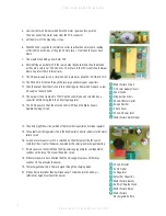
4. Connect pressure tube to lower port of the pressure transducer. Once pressure hits
18mmHg then the pump will stop and only the Lo LED will show.
5. Release the pressure and the pump will restart.
6. If the pressure is below 10mmHg then the pressure mode can not be changed.
7. Apply pressure to transducer. Press the Pressure switch and the Hi LED should light up.
8. When pressure reaches 28mmHg then pump will stop.
9. Apply pressure of over 80mmHg to transducer and the High pressure Audible Warning
should sound. This is a fast beeping with the red Pressure Audible Warning LED flashing.
11. Release all pressure and after 90 secs the low pressure Audible Warning will
be activated. This is a slow beep with the red flashing LED.
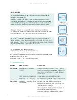
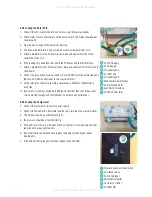
A list of spares and part numbers are available on request from
Direct Healthcare Services
8
10
9
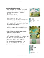
Mute LED
Mute Switch
Pressure Audible Warning LED
Lo LED
Hi LED
Triac (pump switch)
Pressure Switch
Pressure Transducer
5v DC Inlet
240v Inlet
Microprocessor
240v AC Pump Outlet
1
7
2
8
3
9
4
10
5
11
6
12
12
7
3
1
4
2
5 6
11
9. Technical data
9.1. Power Unit (Pump)
Serial Number ............................As per label on rear of pump
Electrical Supply. ...................................220-240 volt, 50 Hz
Power Consumption ...............................................10 watts
Fuses ................................................................TA1H 250V
Protection against shock ...........................................Class 2
Noise Level ...............................................Approx. 30 dB (A)
Dimensions ...........................................235 x 180 x 80 mm
Weight...................................................................... 1.7 kg
Service Interval....................................................12 months
Expected life ............................................................5 years
Shelf life of parts ......................................................5 years
9.2 Mattress
Serial Number .....................Label on inside of mattress cover
Number of Air Cells ................14 Air Cells / 1 Static Foam Cell
Dimensions ........................ 880 x 1980 x 150 mm (Nominal)
Weight.....................................................................13.4kg
Expected life of Mattress ...........................................5 years
Shelf life of Mattress parts .........................................5 years
10. Optimum conditions
(Applies to Mattress and Pump)
10.1 Environment conditions for transport,
storage and use
Transport .................................................... -5˚C – +40˚C
Storage ........................................................5˚C – +40˚C
Usage ........................................................15˚C – +40˚C
Humidity .......................................................... 10% – 93%
Atmospheric Pressure ........................... 700hPa – 1060hPa
Operational Altitude .............................................. ≤ 2000m
10.2 Exposure
Exposure to direct sunlight, dust, lint and general debris is not
considered to be an issue with the Mercury Advance System.


