
4
v5.3 (40026)
© 2005 Directed Electronics, Inc.
Ignition 3
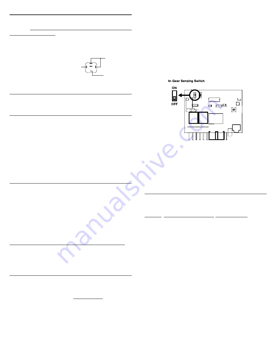
To LARGE 12 Volt
Constant Wire
(Found in Ignition
Switch Wire
Harness)
To Additional
Ignition Wire
(in vehicle)
87
86
White/Black Wire
From
Remote Starter
85
30
87A
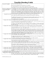
2
flashes
Unit turned off because Brake or Hood was activated.
Check to make sure the hood pin switch is depressed
when the hood is closed and the correct brake wire is
hooked up.
3
flashes
No Tach or Stalled. Review Step 12 and make sure the no
tach/tach wire option is programmed correctly.
4
flashes
Received another remote input from the transmitter (re-
mote pressed before unit completed its cycle)
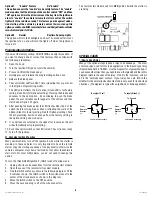
5
flashes
Transmission was shifted into gear. Move the In-Gear
switch inside the receiver module to the OFF position
(see diagram below for location of In-Gear switch inside
module case).
6
flashes
Low battery voltage, or may be missing an ignition wire
which powers up the alternator
8
flashes
Over current - One of the 400 mA (-) transistor outputs
(horn, lights, or Ignition #3) of the control harness is
driving too much current. Make sure to use a relay where
necessary.
12
flashes
The Control Switch was turned off while the starter was
running.
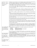
20. Setting Program Features:
The remote starter unit has many special features available. You will
not need to use these special features in most situations. The factory
settings will operate most vehicles.
Feature # Factory Setting (Green LED) Option (Red LED)
1
“No-Tach”
Tach Mode
2
10 Min. Run Time
15 Min. Run Time
3
Normal Crank
Extended Crank
4
N/A
N/A
5
Normal
Ignore Voltage Meter
6
N/A
N/A
7
“Enable” feature
No “Enable”
8
Normal
Daytime Running Lights
Option #1
No-Tach
Tach Mode
This option sets the starting method. The factory setting uses “No-
Tach” starting. If you wish to use the tach to start, follow the instruc-
tions in the Tach Rate Learning section (step 12B).
Option #2
10 Min. Run Time
15 Min. Run Time
This option gives you a choice of run times.
Option #3
Normal Crank
Extended Crank
This option will add 50% more crank time to the NoTach™ starting
feature.
Option #5
Normal
Ignore Voltage Meter
This option allows the minum battery voltage to drop to 11 for re-
mote starting. This option is helpful when dealing with a vehicle
with a poor charging system.
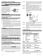
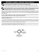
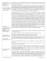
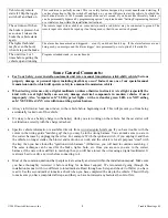
16. White/Black Wire - Ignition #3 - Control Harness
The
WHITE/BLACK
wire, is a ground output that acts just like the
Ignition 1 or Ignition 2 relay outputs (active in the “run” and “crank”
positions).
This wire is a 400 mA negative transistor output and MUST
be set up to power a relay
(not included). It can be used to power the
third ignition wire at the key (necessary for most Ford vehicles).
This is the wire that can also be
used to bypass a passive anti-
theft system by hooking it up
to the Universal Alarm Bypass
Module. See the Factory Anti-
Theft System Section at the end
of the instructions.
REQUIRED FINAL STEPS
You must have hooked up all required wires and completed Initializa-
tion (Step 11) to proceed forward.
17. Trying the Unit Out
WARNING: Be prepared to apply the brake during this testing.
A. Close the hood and fully apply the emergency brake
B. Place the vehicle in Park.
C. Push the On/Off switch once – the red LED will turn on solid Red.
D. Once all the wiring is checked and is correct, press the Start
button on the transmitter.
E. The car should start and continue to run for ten minutes. Make
sure that the engine shuts down if the car is shifted out of park,
the hood is opened, the brake is pressed or the start button is
pushed again. If the car does not start, see Special Cases or Code
Learning section under Special Cases.
18. The Antenna
Feed the antenna around under the dash and up the inside of the
right or left windshield post and over the top of the windshield. Clean
the windshield with the rubbing alcohol pad, wait to dry. Slip the
rubber antenna into the hard plastic antenna clip. Remove the back-
ing from the double sided tape and mount the antenna behind the
rear view mirror. The more exposed the antenna is, the better the
range and performance. Now plug the end of the antenna into the
remote starter module.
In some vehicles you will get better range
performance if the antenna is pointing vertically downward from the
top of the windshield.
The wiring section of the installation is now complete.
Be
sure to cap all unused wires so as to prevent short circuits, and
mount the module securely under the dash. When tying up and
mounting the unit, be sure to avoid any moving parts (steering
column, pedals) and sharp edges.
19. Trouble Shooting with the Self Diagnostics
The remote starter contains a built in diagnostic routine that will
indicate why the unit started or why the unit turned off the car the
last time that the unit was used.
To activate the diagnostic mode for why it turned off, simply turn the
On/Off control switch to the “OFF” position, the LED will turn Green.
In a few seconds, the Green LED on the switch will flash 1 to 12 times
to identify the problem. See the chart below for an explanation of the
flashes:
1
flash
10/15 minute time out. Unit should be fine. Make sure
the transmitter is working properly.


