7
© 2009 Directed Electronics. All rights reserved.
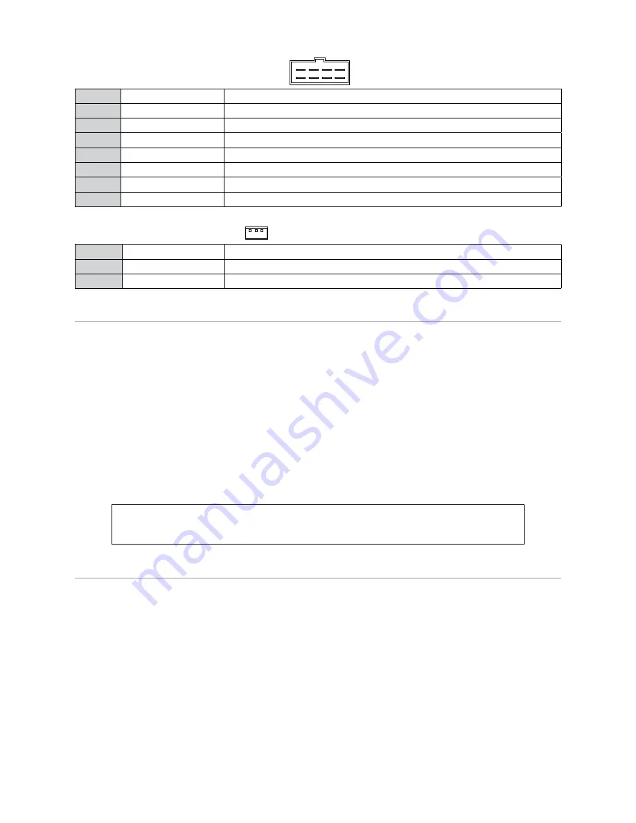
Remote Start, (H3) 8-pin connector
H3/1
PINK
(+) IGNITION 1 INPUT/OUTPUT
H3/2
RED/WHITE
+12V FUSED (30A) IGNITION 2/FLEX RELAY INPUT
H3/3
ORANGE
(+) ACCESSORY OUTPUT
H3/4
VIOLET
(+) STARTER OUTPUT
H3/5
RED
+12V FUSED (30A) IGNITION 1 INPUT
H3/6
PINK/WHITE
IGNITION 2/FLEX RELAY OUTPUT
H3/7
PINK/BLACK
FLEX RELAY INPUT 87a (IF REQUIRED) OF FLEX RELAY
H3/8
RED/BLACK
+12V FUSED (30A) ACCESSORY/STARTER INPUT
Door Lock, 3-pin connector
1
BLUE
(-) 500mA UNLOCK OUTPUT
2
EMPTY
NOT USED
3
GREEN
(-) 500mA LOCK OUTPUT
Initializing Virtual Tach (not needed w/hardwire tach inputs)
To program Virtual Tach:
After the install is complete,
1.
remote start
the engine. The programming operation may require 3 cranks of
the starter before the engine starts and runs. Do not turn off the remote start if this happens, it is a normal
programming operation.
Once the engine begins running, let it run for at least 30 seconds.
2.
Using the Remote, send the Remote start command to turn remote start off. Virtual Tach is programmed.
3.
To reset Virtual Tach, go into the
Reset and Deletion
section of this guide. Virtual Tach
cannot
be reset with
the Bitwriter.
Note:
Virtual Tach cannot be used in MTS Manual Transmission Mode. It is also not recommended for diesel
trucks.
Virtual Tach handles disengaging the starter motor during remote starting – it does not address over-rev. If the
customer wants to have the over-rev protection capability, the tach wire must be connected.
Important:
After successfully learning Virtual Tach, a small minority of vehicle starters
may over crank or under crank during remote start. The Bitwriter can be used fine tune
the starter output time in 50mS increments to compensate for such an occurrence.
Learning the Tach (not needed with Virtual Tach)
To learn the tach signal:
Start
1.
the vehicle with the key. Within 5 seconds,
press
and
hold
the Control button.
After 3 seconds the status LED on your Control Center lights constant when the tach signal is learned.
2.
Release
3.
the Control button.
Note:
When the tachometer is programmed, the main unit automatically enters the Tachometer engine
checking mode.
CPU1
10A FUSE
MINI A
TM
RPN: 8540
LIGHT FLASH POLARIT
Y
(10A (M
AXIMUM) FUSE JUMPER)
+ -
5
8
7
6
1
2
3
4
Bitwriter
Port
Neutral Safety
Switch
Horn Input
Polarity Jumper
1
10
9
8
7
6
1
2
3
4
5
1
1
8
5
1
1
3
10
12
18
10
9
1
1
12
D2D Port (for external
Xpresskit interface module)
10A FUSE
MINI ATM
RPN: 8540
LIGHT FLASH POLARITY
(10A (MAXIMUM) FUSE JUMPER)
+ -
ON
IMPORTANT! Neutral Safety
switch must be plugged in
and in the ON position
D2D jumpers; Factory setting is horizontal position.
Most Xpresskit modules use this setting, check the
Xpresskit installation guide for the specific setting.
RF Port
for IVU
Control Center
Temperature
Sensor
+ -
Main Harness (H1)
(see wiring tables)
H2 Harness
(see wiring tables)
Remote Start (H3)
(see wiring tables)
10A FUSE
MINI A
TM
RPN: 8540
LIGHT FLASH POLARIT
Y
(10A (M
AXIMUM) FUSE JUMPER)
+ -
09
11
10
06
08
07
22
66
88
77
11
1 1
0
11
1 1
0
99
5 5
1
2
1
2
4 4
3 3
ELECTRONICS
R
3
1
4
2
TACH LEARN THREASHOLD
JMP1 OFF
ON
CPU1
NOTE: Pin 1 is on the left
TACH threshold OFF:
TACH threshold ON:
Bitwriter
Port
Neutral Safety
Switch
Remote
Start In
Status
LED
Valet
Port
Door Lock/
Unlock Output
Relay Out
Port
H2
Port
1
10
9
8
7
6
1
2
3
4
5
1
1
8
5
1
1
3
10
12
To change
jumper
settings
1
12


