background image

5

v5.3 (2126)

© 2005 Directed Electronics, Inc.

SPECIAL CASES

1) How to Use a Relay

Many of the optional steps require a relay to be hooked up. The most
common relay used for this type application is the Bosch type relay
(Radio Shack Cat.# 275-226). Use the diagram shown for a typical hookup.
If you have another relay then you need to know that pins 85 and 86 in
this diagram relate to the coils of the relay.  Pin 30 is the ‘common’, and
pin 87 is the ‘normally open’ contact. If your relay has a pin 87A in the
middle it is the normally closed contact and is not used. (The diagram is
typical for alarm disable, horn, or Ignition 3 applications). Relays with
only four terminals, such as RS-275-226 will NOT work for reverse polar-
ity door locks or starter kill.

2) Code Learning

Your transmitter is factory coded to the remote starter


module with

over 16,000,000 different codes.  The remote starter module can
learn the codes of up to 4 different transmitters.  If you want to add
additional transmitters to the receiver or if it does not respond to
your transmitter - follow the steps below to teach the receiver the
transmitter code(s):

A.

Turn the Control Switch ON.

B.

B.

B.

B.

B.

Push the red "code learn" button to the right of the red LED light.
The red LED light and the dash lights come on for a second. (The
vehicles ignition and accessory wires come on).

C.

C.

C.

C.

C.

Hold down the Start button on the transmitter until the red LED
light and the dash lights come on again for a second. The mod-
ule has now learned the transmitter code. Release the transmit-
ter button. The transmitter should be at least a few feet away
from the brain module when doing this.

D

D

D

D

D

..... To learn additional transmitters (up to 3 more), immediately

(within 5 seconds) push the start button on another transmitter
for a few seconds until the red LED light and the dash lights
come on for a second again.

E.

E.

E.

E.

E.

Five seconds after the last time the transmitter was learned the
unit exits the code-learning stage. (The red LED light, ignition
and accessories flash 4 times).

Note:


Teaching the module a new transmitter code will erase all pre-

Option #4

Normal

Super Crank

This option will add 100% more crank time to the NoTach™ starting feature.

Option #5

Normal Voltage Metering

Ignore Voltage Metering

This option is used in the “No-Tach” starting method when the alter-
nator does not turn on quickly after the vehicle is started.

Option #7

“Enable” Feature

No “Enable”

This option cancels the “enable” mode safety feature. The “enable”
mode requires that the driver toggle the ON/OFF control swith “OFF”
then “ON” each time the driver removes the key from the ignition in
order to “enable” the vehicle for remote starter control. This feature
guards against undesired starting of the vehicle by remote control.
You must keep this option as enable on all GM rear-wheel drive and
Dodge Dakota vehicles manufactured prior to 1996.

Option #8

Normal

Daytime Running Lights

This option will turn the headlights on about 10 seconds after it sees
the key in the ignition position – and turn the headlights off when
the key is removed from the ignition. You must hook up the lights
wire in step 13 for the Daytime Running Lights option.

Programming An Option:

If you want the factory setting, DO NOTHING and skip this section.  If
you want to change one or more of the features, TURN THE ON/OFF
CONTROL SWITCH TO THE “OFF” POSITION.  Wait for the red LED
light to stop flashing, then continue with the following procedures:

A.

For options 1-8: Push the white code button on the remote start
module.  Each time you push the button  the red LED light will
flash 1 to 8 times signifying at which feature you are (press it
once, the red LED light flashes once.  Press it again and it will
flash twice.  Press it again and it will flash three times, etc., to
show what feature you are at).

B.

When you are at the feature level you desire, 

push the start

button on the transmitter for 1 second

 and the red LED light will

flash once to signify you are at the  Option setting.  You can push
the transmitter button again and it will flash twice to signify you
are at the Factory setting. Push the transmitter button again and
you will go back to the Option setting (1 flash).

C.

You can choose to change another feature by starting over again
at Step A. or, in six seconds, the remote starter automatically
exits the programming mode (Three red LED light flashes).

D.

When finished – switch the Control Switch back ON.  The red
LED light will flash once.

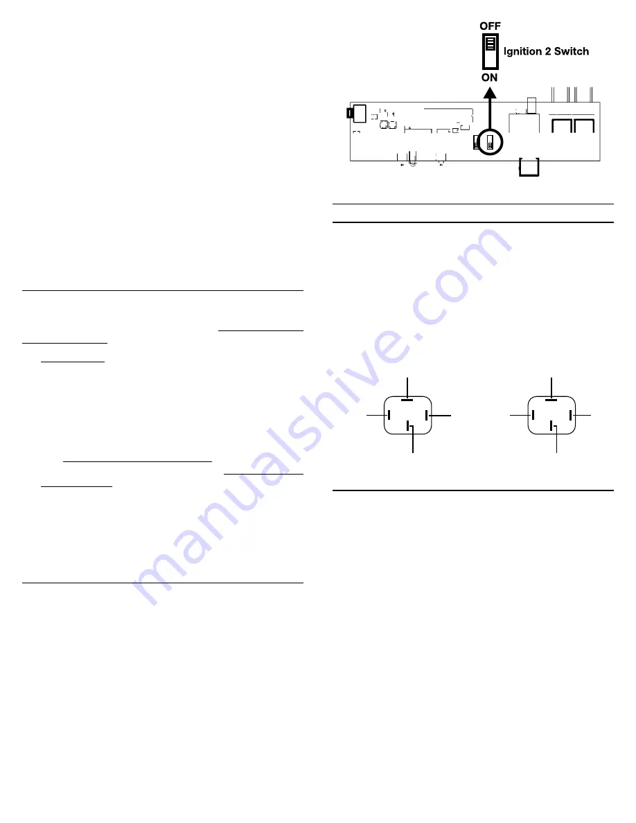
21. Changing Ignition 2 Function

Many vehicles turn off the Ignition 2 wire while the starter is crank-
ing. In these vehicles it is very important to have the remote starter
copy the starting sequence of the key exactly; otherwise the vehicle's
computer may show a fault code. Our vehicle wiring database on our
website will help you determine the correct IGN 2 wire for your ve-
hicle.

To turn the thick GREEN Ignition 2 wire off during crank:

1.

Unplug all wires and connections from the remote start module.

2.

Open the case of the remote start receiver module.

3.

Look for the small IGN2 switch as shown in the following dia-
gram.

4.

Move the IGN2 switch to the OFF position.

5.

Close the case and plug in all of the wire connectors.

The remote starter will turn off Ignition 2 while the starter is crank-
ing.

From
Remote 
Starter
(-)

To Vehicle's Accessory

+12 V

87

86

85

30

To Ground

To Vehicle's Accessory

+12 V

87

86

From
Remote 
Starter
(-)

85

30

+12 V

To 12 volt output

To supply Ground (-) output

Summary of Contents for Ready Remote 23926

Page 1: ...our car Starts the vehicle automatically when ever the temperature drops below 0 F 18 C when the Cold Start option is activated Will shut off if the brake pedal is pushed the hood is opened or the transmission is shifted out of park unless the key is in the ignition and in the run position Is quality engineered and microprocessor controlled to provide many years of reliable use Comes with a Limite...

Page 2: ... insert the 30 amp green fuse into the holder until step 11 As the power is first applied to the unit the red diagnostic LED light will blink once Note Failure to properly install the fuse holder and 30 amp fuse to the pink wire to the battery voids all product warranties Ignition Key Diagram for Steps 4 7 The vehicle s wires are found coming off of the key switch Remove the panel under the steeri...

Page 3: ...before starting the ve hicle This wire can be used to turn off the factory alarm system in vehicles which have them In most vehicles this wire is located in the driver s kick panel A relay is needed for vehicles which require a positive pulse you may share the wiring but be sure to diode isolate each wire going to the hood pin switch with the bands of diodes pointing towards the pin switch as show...

Page 4: ...utputs active in the run and crank positions This wire is a400mAnegativetransistorout put and MUST be set up to power a relay not included It can be used to power the third ignition wire at the key necessary for most Ford vehicles This is the wire that can also be used to bypass a passive anti theft system by hooking it up to the Universal Alarm Bypass Module See the Factory Anti Theft Systems sec...

Page 5: ...to enable the vehicle for remote starter control This feature guards against undesired starting of the vehicle by remote control You must keep this option as enable on all GM rear wheel drive and Dodge Dakota vehicles manufactured prior to 1996 Option 8 Normal Daytime Running Lights This option will turn the headlights on about 10 seconds after it sees the key in the ignition position and turn the...

Page 6: ...onder Honda Prelude 98 Transponder Honda S2000 Transponder Infinity I30 98 Transponder Infinity Q45 98 Transponder Infinity QX4 Transponder Isuzu Hombre 98 Passlock II Jaguar all 98 Transponder Jeep Grand Cherokee 99 Transponder Jeep TJ Wrangler 99 Transponder Lexus all 97 Transponder Lincoln Continental 97 P A T S Lincoln LS 2000 P A T S Lincoln Mark VIII 97 P A T S Lincoln Navigator 97 P A T S L...

Page 7: ...ds in the field of advanced electronic technology DIRECTED is ISO 9001 registered Quality Directed Electronics products are sold and serviced throughout North America and around the world Call 800 274 0200 for more information about our products and services Directed Electronics is committed to delivering world class quality products and services that excite and delight our customers Directed Elec...

Page 8: ...is period so long as the Unit remained installed in the original vehicle Directed will at its option repair or replace this Unit if it is proved defective in workmanship or material PROVIDED the Unit is returned to Directed s warranty department at One Viper Way Vista CA 92081 along with 20 postage and handling fee a bill of sale or other dated proof of purchase bearing the following information D...

Page 9: ...xide build up Available Accessories Universal Alarm Bypass Module allows remote car starter installation on newer vehicles with factory anti theft systems such as VATS P A T S Passlock I Passlock II Pass Key III Saturn Securlock and Transponder systems Extra transmitters for more than one user in the family Up to four transmitters can be used with each receiver in the vehicle Directed Electronics ...

Page 10: ...ly set that option Try re setting the unit Unplug everything from the module except the black ground wire and LED if you have a plug in LED While pressing the white button on the module connect the power lead The LED on the unit should turn on and stay on Release the white push button and the LED should remain illuminated If not repeat the process being sure to hold in the white button while conne...

Page 11: ...ched if you have been instructed by a technician to do so or you are getting a diagnostic code of 5 flashes Your vehicle may not have a neutral safety switch such as pre 95 GM rear wheel drive vehicles or Dodge Dakotas built prior to 1996 Try this Open the hood and place your foot on the brake Start the vehicle with the key Turn the engine off and release the brake If all of your connections are c...

Page 12: ... change Repeat again to verify if you get the same voltage every time then the module is set up perfectly There is no chart to help you with this it is just trial and error but it will work regardless of the meter you are using Can I use the DesignTech Transmitter with other brands of products NO Due to proprietary technology DesignTech brand products will operate only with DesignTech brand Transm...

Page 13: ... real light bulb can severely damage electrical components in modern vehicles if used improperly Also computer safe LED type test lights with a red and or green LED are NOT airbag safe NEVER test ANY wire within an airbag system harness Always roll down at least one window in the vehicle before beginning work This will prevent you from being accidentally locked out of the vehicle It s okay to have...

Page 14: ...n driver kick panel Cadillac Allante 1993 YELLOW PINK VIO WHT VATS ORANGE LT BLUE WHITE LT GREEN BROWN BLACK in driver kick panel Fleetwood RWD 1990 96 YELLOW PINK N A VATS ORANGE WHITE OR BLUE WHITE LT GREEN BROWN BLACK in driver kick panel may be equipped with VATS Coupe DeVille 1992 93 YELLOW PINK N A N A ORANGE LT BLUE WHITE LT GREEN BROWN BLACK in driver kick panel Eldorado 1992 94 YELLOW PIN...

Page 15: ... N A BLK ORNG WHITE TAN BLK GRAY GREEN ORNG BLACK YELLOW BLK RED Late Model Require resistor value to Disarm Intrepid 1998 02 YELLOW BLUE WHT GRN RED TRANSPONDER BLK ORG WHITE TAN TAN PINK GREEN ORANGE BLACK YELLOW BLK RED 2000 are equipped with Transponder key Intrepid 1996 97 YELLOW BLUE RED WHT N A BLK ORG WHITE TAN RED WHITE BLACK YELLOW BLK RED at fact keyless mod on top of dash Neon 1995 02 ...

Page 16: ...L N A GREEN RED BLK ORANGE 3 2L wire is BLK RED Prelude 1997 02 BLK WHT BLK YEL YELLOW N A WHT BLK GREEN WHITE BLUE N A RED BLACK N A 98 are equipped with transponder key Prelude 1987 96 BLK WHT BLK YEL YELLOW N A WHT BLK GREEN BLUE N A RED BLACK BLUE BLACK Hummer General Hummer 1992 98 Drk Green Lt Green Gray N A Orange Red White Hyundai Accent 2000 02 WHITE GREEN YELLOW N A BLUE PINK BLACK BLUE ...

Page 17: ...EN PURPLE BROWN D BLUE Equipped with Transponder Towncar 1998 02 RED LTBLU WHITE YEL GRAY YEL PINK BLK BLK LT GRN LT GREEN WHITE RED N A BROWN DK BLUE Towncar 1992 97 WHT PINK BRWN PINK PINK BLACK BLK GREEN RED GREEN LT GREEN TAN YELLOW DK GREEN PURPLE BROWN DK BLUE Has a second acc wire Black lt Green Mazda 626 2000 02 GREEN BLACK WHT BLACK RED N A BLUE WHITE GREEN RED RED WHITE GREEN RED Equippe...

Page 18: ...WHITE BLACK RED N A N A WHITE BLUE RED GREEN BLUE BLACK N A RED BLUE GRN WHITE Xterra 2000 04 BLACK YEL BLK WHITE RED YEL N A WHITE BLUE GREEN YEL PINK BLUE L GREEN BLUE RED LGRN BLACK OLDSMOBILE Acheiva 1993 98 YELLOW PINK WHITE N A ORANGE WHITE WHITE N A BROWN BLACK Alero 1999 01 YELLOW PINK DK GREEN N A ORANGE WHITE VIOLET WHT N A BROWN BLACK Equipped with passlock II Arora 2001 02 PURPLE PINK ...

Page 19: ...REEN GREEN RED Echo 2000 01 BLACK BLACK RED BLACK YEL N A WHITE BLUE GREEN WHITE GREEN RED BLUE YELLOW GREEN WHITE RED NEED RELAY FOR STARTER INTERUPT Land Cruiser 1999 02 BLK WHT BLUE BLK BLK RED N A BLACK GREEN WHITE BLACK N A GREEN GREEN ORG Land Cruiser 1991 97 BLK WHT Blk Red or Blk GRN BLACK YEL N A BLUE RED GREEN WHITE BLACK N A GREEN GREEN RED Land Cruiser 1998 BLK WHT BLK BLUE BLK RED N A...

Reviews: