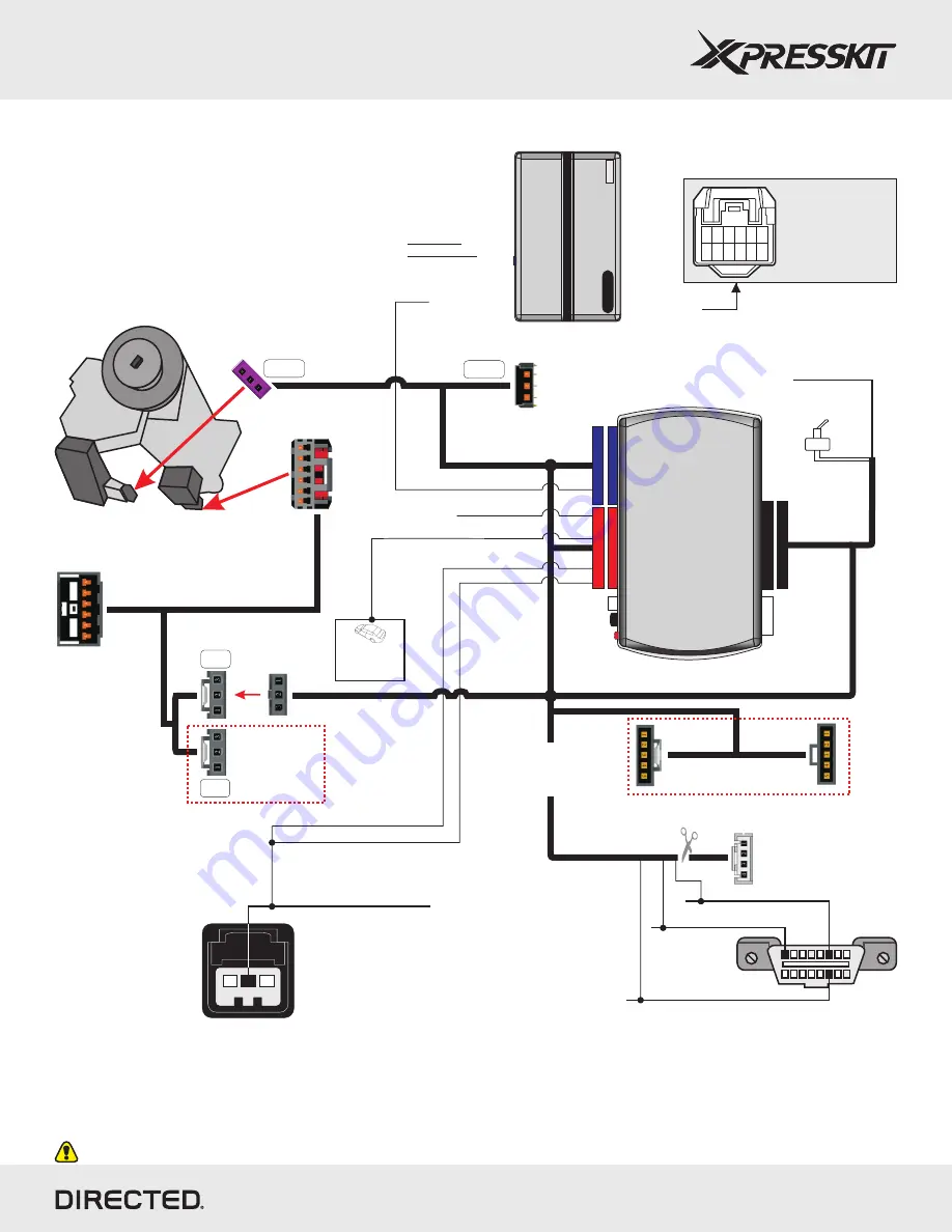
Light Switch
Connector
(-) Parking Lights
Refer to the Vehicle
Wiring Reference Chart
(pages 4, 5, 6, and 8) for
wire color and location.
Installation with T-Harness
(for all GM10 vehicles)
Page 9
Wires are listed by pin numbers. This display is not representative of connector pin layouts, which are often stacked.
* If the RAP OFF wire is not connected, the radio will turn OFF but some lights will remain ON in the central console for 10 minutes. Connect this wire
(Green/Black, pin 2/12) to the driver door sense trigger (Gray/Black) to avoid the issue.
(-) Parking Lights
R
e
m
o
te
S
ta
rt
e
r
(+) Ignition Output
(-) Hood Status Input
(+) 12v
(+) 12v
(-) Ground
(-) Ground
1
0
DBALL
RF
Programming button
LED
4
1
4
1
2
2
TX
(-) Ground
RX
(+) 12v
Remote Start Safety
Override Switch
Theft
Deterrent
Module (TDM)
connector
Vehicle side
to vehicle
6-pin connector
Ignition
Connector
To Theft Deterrent Module (TDM)
(under ignition switch,
black connector)
Use connectors
labeled GM10
NOT USED
NOT USED
2: Green/Black: (-) RAP OFF *
Black/White: NC
Cut away the 4-pin
connector and connect
the three wires to the
OBDII 16-pin connector.
(-) Driver
Door Sense
Trigger*
Diagnostic connector
OBDII (connector side view)
1
8
16
9
Can HIGH
Tan/Black or Blue: pin 6
Can LOW
Tan or White: pin 14
SW CAN
Lt. Green: pin 1
3
1
9: Purple/Green: N.C.
8: Purple/Brown: N.C.
Pink: Ignition Output.
White/Black: N.C.
B
A
C
Clutch Switch
(black connector)
For manual
transmission
vehicles only.
Yellow
(On the Camaro and Cruze vehicles)
T-Harness
THGM610
(Optional)
6
12
1
7
GM10
GM10
Ignition
Barrel
T-01
T-02
Rev.: 20130304
Platform: DBALL
Firmware: GM10 v. 2.08+
© 2012 Directed. All rights reserved.


