6
©
2005
Directed Electronics, Inc.
Main Harness (N1) Wire Connection Guide
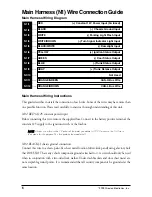
Main Harness Wiring Diagram
___
___
___
___
___
___
___
___
___
___
___
___
Main Harness Wiring Instructions
This guide describes in detail the connection of each wire. Some of the wires may have more than
one possible function. Please read carefully to ensure a thorough understanding of this unit.
N1/2 RED (+)12V constant power input
Before connecting this wire, remove the supplied fuse. Connect to the battery positive terminal, the
constant 12V supply to the ignition switch, or the fusebox.
N
NO
OTTEE: Always use a fuse within 12 inches of the point you obtain (+)12V. Do not use the 5 A fuse in
the harness for this purpose. This fuse protects the module itself.
N1/2 BLACK (-) chassis ground connection
Connect this wire to a clean, paint-free sheet metal location (driver kick panel) using a factory bolt
that DOES NOT have any vehicle component grounds attached to it. A screw should only be used
when in conjunction with a two-sided lock washer. Under dash brackets and door sheet metal are
not acceptable ground points. It is recommended that all security components be grounded at the
same location.
ORANGE/BROWN
CAN-L Bus Wire
ORANGE/GREEN
CAN-H Bus Wire
Not Used
GRAY
(+) Trunk Release Output
BLUE
(-) Trunk Status Output
GREEN
(-) Door Status Output
YELLOW
(+) Ignition Status Output
BLACK/WHITE
(-) Domelight Input
WHITE/BROWN
(-) Turn Signal Indicator Light Input
WHITE
(-) Parking Light Flash Input
BLACK
(-) Chassis Ground Input
RED
(+) Constant 12V Power Input (5A fused)
N1/1
N1/2
N1/3
N1/4
N1/5
N1/6
N1/7
N1/8
N1/9
N1/10
N1/11
N1/12


