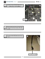
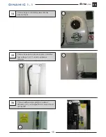
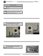
background image

Instrucciones de Montaje

Mounting Instructions

Instructions de Montage

Montageanweisungen

Istruzioni di Montaggio

220.AA1.1008

ES

Spanish

English

French

German

Italian

EN

FR

GE

IT

DINAMIC


1.1

12 V

dirna

, s.a.

Acondicionadores de aire para vehículos

Summary of Contents for bycool Dinamic 1.1

Page 1: ...je Mounting Instructions Instructions de Montage Montageanweisungen Istruzioni di Montaggio 220 AA1 1008 ES Spanish English French German Italian EN FR GE IT DINAMIC 1 1 12 V dirna s a Acondicionadores de aire para vehículos ...

Page 2: ...xenta de responsabilidad si se producen averías que procedan de una inadecuada manipulación ó instalación del equipo ó por mo dificaciones y sustituciones efectuadas sin nuestra expresa autorización por escrito Cantidad de carga de gas refrigerante R 134a a introducir en el circuito 300 gr Véase procedimiento de garantía del producto incluido en Diagnosis de Averías Véase Manual de Usuario del equ...

Page 3: ...cama presentar plantilla por encima de la cama OPERACIONES PREVIAS Desconectar batería Desmontar tapa de unidad evaporadora 2 Dar taladro Ø4 pasante con broca larga en posición de taladro Ø48 después efectuar los siguientes taladros A dar 1 Ø35 sólo en el tapizado B dar 1 Ø19 sólo en el tapizado C dar 1 Ø48 sólo en el tapizado D dar 4 Ø22 sólo en el tapizado 1 2 ARRIBA ARRIBA ARRIBA ARRIBA 3 2D 2C...

Page 4: ...ma plana y tuerca autoblocante sujetando por parte interior con llave de tubo 10 Pasar tubo desagüe por taladro Ø19 por el pasamuros hacia el interior cabina Colocar tapones de tuerca y pasamuros 4 7 5 6 6 3 POR EXTERIOR CABINA Presentar plantilla a nivel por exterior tomando como referencia el taladro efectuado Ø4 y marcar y dar taladros restantes ...

Page 5: ...posición de taladro Ø48 después efectuar los siguientes taladros A dar 1 Ø19 B dar 1 Ø48 C dar 4 Ø7 Efectuar los siguientes taladros B dar 1 Ø19 sólo en el tapizado C dar 1 Ø48 sólo en el tapizado D dar 4 Ø22 sólo en el tapizado OPERACIONES SÓLO VÁLIDAS PARA MODELOS RENAULT MAGNUM Ø48 Ø19 4 Ø7 1 3C 3A 3B ARRIBA ARRIBA OPERACIONES PREVIAS Desconectar batería Desmontar tapa de unidad evaporadora Ø48...

Page 6: ...como se indica Fijar por el exterior con arandela de goma plana y tuerca autoblocante sujetando por parte interior con llave de tubo 10 Colocar tapones de tuerca y pasamuros Pasar tubo desagüe por taladro Ø19 por el pasamuros hacia el interior cabina 6 7B 7 7A 7A OPERACIONES SÓLO VÁLIDAS PARA MODELOS RENAULT MAGNUM ...

Page 7: ...erior hacia fuera para evitar que el agua de condensación caiga al tapizado Pasar tubo desagüe por taladro de la base del evaporador y conectar a la bandeja 8 9 10 Pasar cableados por taladro Ø 35 hacia el exterior 10 10 Tuerca M6 Arandela plana ala ancha Tuerca M6 dejar a la altura del tapizado Bandeja de desagüe Soporte evaporador Tapizado Base evaporador Tapizado Tuerca M6 Chapa camión Tuerca M...

Page 8: ...evaporador sobre espárragos y Fijar con 4 arandelas planas 4 grower y 4 tuercas M6 MUY IMPORTANTE El desagüe debe quedar con la suficiente caída para evitar la caída del agua al tapizado Conectar sonda recirculación y cable de comunicaciones 11 11 12 ...

Page 9: ...9 DINAMIC 1 1 dirna s a ES 13 Volver a fijar frente con sus tornillos usando destornillador inmantado y colocar tapones 13 13 13 ...

Page 10: ...ador Desmontar tapa y soltar el cableado del electro Si se realiza entre 2 personas Presentar la base del condensador situandola en la parte trasera de la cabina mas idónea teniendo en cuenta la longitud de tubería desde la salida del evaporador al condensador y fijar mínimo 6 taladros Dar primero los 2 Taladros superiores X a Ø 9 colocar tuercas remache de M6 y posicionar la base con tornillos 6 ...

Page 11: ... 40 mm y tornillo 6 100x40 60 70 VER DETALLE A 5 DETALLE A Tuerca remache M6 Parte trasera cabina 6 100x40 60 70 Soporte Separador 10 mm Separador 20 mm 6 100x30 Arandela grower Ø 6 Arandela plana Ø 6 ala ancha Parte trasera cabina 6 Fijar Unidad con 8 tornillos 6 100X30 arandela grower y plana 6 ...

Page 12: ...7 Conectar cableado y racores en evaporador y sellar con cinta antigoteo 7 8 Conectar tuberías y cableado en unidad condensadora En caso de ser necesario colocar racor de empalme 90º LADO IZQUIERDO LADO DERECHO LADO DERECHO 8 8 8 ...

Page 13: ...a Presentar protector de tuberías con junta marcar y taladrar a Ø4 y fijar con tornillos rosca chapa 4 8x19mm Pegar soportes de plástico y fijar tubería cableados y tubo desagüe limpiar zona montaje Colocar válvula de drenaje 9 10 10 10a ...

Page 14: ...tar en batería cableado alimentación ATENCIÓN A LA POLARIDAD Pasar cableado por la zona mas idonea hacia la unidad condensadora fijando c abrazaderas o bridas Conectar cableado alimentación con el de la unidad 11 FUSIBLE 13 Conectar a la unidad ...

Page 15: ...apa con tornillos desmontados anteriormente Colocar tapa protectora de racores c tornillos rosca chapa 3 1x 11 en lado opuesto a tuberias 14 14 15 16 Colocar adhesivos de peligro en unión cableado A y en dispositivo de elevación de cabina B A B ...

Page 16: ...18 19 20 Hacer vacío en el circuito durante al menos 30 minutos Introducir 300 gr de carga de gas R134a y poner el equipo en marcha VISTA GENERAL DE LA UNIDAD CONDENSADORA Y TUBERÍA VISTA GENERAL DE LA UNIDAD EVAPORADORA CARGA DE GAS ...

Page 17: ...carse ninguna tecla ni del panel ni del mando del equipo porque se pueden producir daños irreparables A la señal de estos pitidos discontinuos desconectar el equipo de la batería y verificar la polaridad de la conexión SOPLADOR SONDA DE TEMPERATURA SONDA ANTIHIELO CONTROL ELECTRÓNICO MÓDULO DE CONTROL MÓDULO DE COMPRESOR ELECTRO BATERÍA FUSIBLE COMPRESOR Az Azul N Negro R Rojo V Verde B Blanco A A...

Page 18: ...from an inadequate han dling or installation of the equipment or from mo difications and substitutions carried out without our express and written authorisation Amount of refrigerant gas load R 134a to be introduced in the circuit 300 g Please see product warranty procedure included in Troubleshooting diagnosis Please see equipment User s Guide for its correct functioning of the remote control and...

Page 19: ...e is 1 bed place the template on the bed PRIOR OPERATIONS Disconnect the battery Dismount the evaporation unit cover 2 Make through bore Ø4 with long broach in bore position Ø48 and then make the following bores A make 1 Ø35 in the cover only B make 1 Ø19 in the cover only C make 1 Ø48 in the cover only D make 4 Ø22 in the cover only 1 2 ARRIBA ARRIBA ARRIBA ARRIBA 3 2D 2C 2D 2A 2B ...

Page 20: ...sher and a self locking nut securing at the bottom with a socket wrench of 10 Pass the waste water pipe through the bore of Ø19 through the bushing towards the inside of the cabin Position bushing and nut covers 4 7 5 6 6 3 CABIN EXTERIOR Introduce the template level using the exterior taking as reference the Ø4 bore made mark and make the remaining bores ...

Page 21: ...long broach in bore position Ø48 and then make the following bores A make 1 Ø19 B make 1 Ø48 C make 4 Ø7 Make the following bores B make 1 Ø19 in the cover only C make 1 Ø48 in the cover only E make 4 Ø22 in the cover only OPERATIONS ONLY VALID FOR RENAULT MAGNUM MODELS Ø48 Ø19 4 Ø7 1 3C 3A 3B UP UP PRIOR OPERATIONS Disconnect the battery Dismount the evaporation unit cover Ø48 225 mm 16 mm 3 5D 5...

Page 22: ... Secure the exterior with a rubber washer a flat washer and a self locking nut securing at the bottom with a socket wrench of 10 Position bushing and nut covers Pass the waste water pipe through the bore of Ø19 through the bushing towards the inside of the cabin 6 7B 7 7A 7A OPERATIONS ONLY VALID FOR RENAULT MAGNUM MODELS ...

Page 23: ...e towards the exterior 10 10 M6 Nut Wide ring flat washer M6 Nut leave at upholstery height Evaporator base Upholstery M6 Nut Lorry sheet M6 self blocking nut Protector cap Rubber washer Wide ring flat washer Wide ring flat washer M6 Stud OUTSIDE INSIDE VERY IMPORTANT In the case of slanting upholstery the evaporator unit must be vertical or sloping from the lower section to the outside in order t...

Page 24: ...ator base on the studs and secure with 4 flat washers 4 Grower washers and 4 M6 nuts Connect recirculation probe and communications wiring 11 11 12 VERY IMPORTANT The wastewater run off must be sufficient to prevent water from dropping onto the upholstery ...

Page 25: ...25 DINAMIC 1 1 dirna s a EN 13 Secure the front with its screws using a magnetic screwdriver and position the covers 13 13 13 ...

Page 26: ... condenser Dismount the cover and release the electro cabling If this is carried out by 2 people introduce the capacitor base placing it at the most appropriate part of the rear of the cabin taking into account the pipe length from the evaporator to the condenser and secure with at least 6 bores First make the 2 upper bores X at Ø 9 position M6 rivet nuts and position the base with screws 6 100x30...

Page 27: ...rator and 6 100x40 60 70 screw SEE DETAILS A Secure the unit with 8 6 100X30 screws grower washer and flat washer supported flat 5 DETAIL A M6 riveting nut Rear cabin part 6 100x40 60 70 Support 10 mm Separator 20 mm Separator 6 100x30 Ø 6 grower washer Ø 6 wide ring flat washer Rear cabin part 6 ...

Page 28: ... 1 EN 7 8 Connect cabling and adapters in the evaporator and seal with drip proof tape Connect pipes and cabling in condensation unit 7 LEFT SIDE RIGHT SIDE RIGHT SIDE 8 8 8 If it is necessary to position 90 hose connection ...

Page 29: ...ntroduce pipe protector with flange mark and bore at Ø4 and secure with threaded metal screws of 4 8x19mm Stick the plastic supports and secure the pipe cabling and wastewater pipe clean the assembly area Position drainage valve 9 10 10 10a ...

Page 30: ...13 Connect power cabling in battery TAKE CARE WITH POLARITY Pass the cabling through the most appropriate area towards the condensation unit securing with clamps or flanges Connect power cables to the unit 11 FUSE 13 Connect to the unit ...

Page 31: ...ion the cover with the previously dismounted screws Position adapter protection cover with metal threaded screws 3 1x 11 on the side opposite the pipes 14 15 16 Place danger stickers on the cable join A and on the cab elevation device B A B ...

Page 32: ...IC 1 1 EN 17 18 19 20 Empty the circuit for at least 30 minutes Introduce 300 g of gas load R134a and start up the equipment GENERAL VIEW OF THE CONDENSATION UNIT AND PIPING GENERAL VIEW OF THE EVAPORATION UNIT GAS LOAD ...

Page 33: ...e beeps Do not touch any keys on the equipment switchboard or panel as this may produce irreparable damage If you hear the beeps disconnect the equipment from the battery and check the connection polarity BLOWER TEMPERATURE PROBE ANTIFREEZE PROBE ELECTRONIC CONTROL MODULE CONTROL COMPRESSOR ELECTRONIC MODULE FAN BATTERY FUSE COMPRESSOR Az Blue N Black R Red V Green B White A Yellow Na Orange M Bro...

Page 34: ... des dommages ou des bris dérivés d une installation ou d une manipulation incorrecte ni des modifications réalisées sans autorisation expresse par écrit Quantité de charge de gaz réfrigérant R 134a à introduire dans le circuit 300 gr Voir la procédure de garantie du produit au Diagnostic de problèmes Voir le Guide de l Usager de l appareil pour le fonctionnement correcte de la télécommande et du ...

Page 35: ...u berceau OPERATIONS PREVUES Démonter batterie Démonter couvercle de l unité d évaporation 2 Procéder au perçage Ø4 en traversée avec une broche longue en position de perçage Ø48 ensuite effectuer les perçages suivants A Perçage 1 Ø35 seulement dans la tapisserie B Perçage 1 Ø19 seulement dans la tapisserie C Perçage 1 Ø48 seulement dans la tapisserie D Perçage 4 Ø22 seulement dans la tapisserie 1...

Page 36: ... auto serrant en fixant par la partie intérieure avec la clé à tube 10 Passer le tuyau d évacuation par le perçage Ø19 la traversée vers l intérieur de la cabine Placer les bouchons des écrous et traversées 4 7 5 6 6 3 PAR L EXTERIEUR DE LA CABINE Présenter modèle au niveau par l extérieur en prenant pour référence le perçage effectué Ø4 et marquer et effectuer les perçages restant ...

Page 37: ... Ø48 puis effectuer les perçages suivants A perçage 1 Ø19 B perçage 1 Ø48 C perçage 4 Ø7 Effectuer les perçages suivants B Perçage 1 Ø19 uniquement dans la tapisserie C Perçage 1 Ø48 uniquement dans la tapisserie E Perçage 4 Ø22 uniquement dans la tapisserie OPERATIONS VALABLES UNIQUEMENT POUR LE MODELE RENAULT MAGNUM Ø48 Ø19 4 Ø7 1 3C 3A 3B HAUT HAUT OPERATIONS PRELIMINAIRES Déconnecter la batter...

Page 38: ...indiqué Fixer par l extérieur avec une rondelle en caoutchouc plane et écrou auto serrant en fixant par l intérieur avec une clé à tube 10 Placer les bouchons d écrous et traversées Passer le tuyau d évacuation par le perçage Ø19 la traversée vers l intérieur de la cabine 6 7B 7 7A 7A OPERATIONS VALABLES UNIQUEMENT POUR LE MODELE RENAULT MAGNUM ...

Page 39: ...lle plate à large papillon Écrou M6 laisser à la hauteur de la tapisserie Base évaporateur Tapisserie Écrou M6 Tôle camion Écrou M6 autobloquant Bouchon protecteur Rondelle en caoutchouc Rondelle plate à large papillon Rondelle plate à large papillon Goujon M6 EXTÉRIEUR INTÉRIEUR TRÈS IMPORTANT Dans le cas des tapisseries qui présentent une inclinaison l ensemble évaporateur doit rester vertical o...

Page 40: ...aporateur sur goujons et fixer avec 4 rondelles planes 4 grower et 4 écrous M6 TRÈS IMPORTANT L écoulement doit présenter une chute suffisante pour éviter que l eau atteigne la tapisserie Connecter sonde de recirculation et câble de communications 11 11 12 ...

Page 41: ...41 DINAMIC 1 1 dirna s a FR 13 Fixer à nouveau la façade avec les vis à l aide d un tournevis aimanté et placer les bouchons 13 13 13 ...

Page 42: ...desserrer le câblage de l électro Si cette opération est effectuée par 2 personnes Présenter la base du condensateur en la situant par la partie arrière de la cabine qui conviendra le mieux en tenant compte de la longueur de la tuyauterie depuis la sortie de l évaporateur au condensateur et établir un minimum de 6 perçages Effectuer d abord les 2 perçages supérieurs X à Ø 9 placer les écrous rivet...

Page 43: ...e 10 20 40 mm et une vis 6 100x40 60 70 VOIR DETAILA Fixer l unité avec 8 vis 6 100X30 rondelle grower et plane 5 DETAIL A Écrou à rivet M6 Partie arrière cabine 6 100x40 60 70 Support Écarteur 10mm Écarteur 20 mm Écarteur 40 mm 6 100x30 Rondelle grower Ø6 Rondelle plate Ø6 à large papillon Partie arrière cabine 6 ...

Page 44: ...âblage et les raccords sur l évaporateur et sceller avec ruban anti égouttement Connecter les tuyauteries et câblage dans l unité de condensation 7 CÔTE GAUCHE CÔTE DROIT CÔTE DROIT 8 8 8 Si il est nécessaire de positionner le tuyau de connexion 90 ...

Page 45: ...cteur de tuyaux avec joint marquer et percer à Ø4 puis fixer avec des vis taraudeuse à tôle 4 8x19mm Coller les supports en plastique et fixer la tuyauterie les câblages et le tuyau d évacuation nettoyer zone de montage Placer vanne de drainage 9 10 10 10a ...

Page 46: ...sur batterie câblage d alimentation ATTENTION À LA POLARITE Passer le câblage par la zone la plus indiquée vers l unité de condensation en fixant avec des brides Connecter le câblage d alimentation à celui de l unité 11 FUSIBLE 13 Connecter l unité ...

Page 47: ... vis démonté précédemment Placer le couvercle de protection de raccords avec des vis taraudeuses à tôle 3 1x 11 du côté opposé à la tuyauterie 14 15 16 Placer des adhésifs de danger à l union de câblage A et sur le dispositif d élévation de la cabine B A B ...

Page 48: ... 18 19 20 Vider le circuit durant au moins 30 minutes Introduire 300 gr de charge de gaz R134a et mettre l équipement en marche VUE GENERALE DE L UNITÉ DE CONDENSATION ET TUYAUTERIE VUE GÉNÉRALE DE L UNITÉ ÉVAPORATRICE CHARGE DE GAZ ...

Page 49: ...e touche du tableau ni de la com mande de l équipement car il pourra se produire des dommages irréparables Au signal de ces sifflements discontinus déconnecter l équipement de la batterie et vérifier la polarité de la connexion SOUFFLANTE SONDE TEMPÉRATURE SONDE ANTIGEL CONTRÔLE ÉLECTRONIQUE MODULE ÉLECTRONIQUE MODULE ÉLECTRONIQUE Electroventilateur BATTERIE FUSIBLE COMPRESSEUR Az Bleu N Noir R Ro...

Page 50: ...ung für Schäden oder Brüche aufgrund einer nicht ordnungsgemäßen Installation oder Bedienung des Geräts oder den Austausch von Teilen bzw Umbauten die ohne die erforderliche schriftliche Genehmigung durchgeführt wurden In den Kühlkreis zu leitende Füllmenge Kühlgas R 134a 300 g Siehe Garantieverfahren des Produkts in der Fehlerdiagnose Siehe Benutzerleitfaden des Geräts für den ordnungsgemäßen Bet...

Page 51: ...vorhanden Vorlage über diesem auflegen VORBEREITENDE TÄTIGKEITEN Batterie abschalten Abdeckung Verdampfereinheit abnehmen 2 Durchgangsbohrung Ø4 mit langem Bohrer in Position der Bohrung Ø48 durchführen danach die folgenden Bohrungen durchführen A 1 Ø35 nur im Bezug durchführen B 1 Ø19 nur im Bezug durchführen C 1 Ø48 nur im Bezug durchführen D 4 Ø22 nur im Bezug durchführen 1 2 ARRIBA ARRIBA ARRI...

Page 52: ... Spannmutter befestigen dabei von Innen her mit Rohrschlüssel 10 halten Abflussschlauch durch Bohrung Ø19 und Wanddurchführung ins Innere der Kabine führen Mutterkappen und Wanddurchführung anbringen 4 7 5 6 6 3 AUF DER KABINENAUSSENSEITE Vorlage auf gleicher Höhe von der Außenseite auflegen dabei als Referenz die durchgeführte Ø4 Bohrung nehmen markieren und die restlichen Bohrungen durchführen ...

Page 53: ...Ø48 durchführen danach die folgenden Bohrungen durchführen A 1 Ø19 durchführen B 1 Ø48 durchführen C 4 Ø7 durchführen Die folgenden Bohrungen durchführen B 1 Ø19 nur im Bezug durchführen C 1 Ø48 nur im Bezug durchführen E 4 Ø22 nur im Bezug durchführen NUR BEI DEN MODELLEN RENAULT MAGNUM DURCHZUFÜHRENDE TÄTIGKEITEN Ø48 Ø19 4 Ø7 1 3C 3A 3B OBEN OBEN VORBEREITENDE TÄTIGKEITEN Batterie abschalten Abd...

Page 54: ...en Von Außen her mit Gummiunterlegscheibe Flachscheibe und selbstsichernder Spannmutter befestigen dabei von Innen her mit Rohrschlüssel 10 halten Mutterkappen und Wanddurchführung anbringen Abflussschlauch durch Bohrung Ø19 und Wanddurchführung ins Innere der Kabine führen 6 7B 7 7A 7A NUR BEI DEN MODELLEN RENAULT MAGNUM DURCHZUFÜHRENDE TÄTIGKEITEN ...

Page 55: ...n 8 9 10 Kabel durch die Bohrung Ø 35 nach Außen führen 10 10 M6 Mutter Breitflansch Flachscheibe M6 Mutter bündig auf Polsterung Verdampfergrundplatter Polsterung M6 Mutter Lkw Blech Selbstsichernde M6 Mutter Schutzdeckelr Gummischeibe Breitflansch Flachscheibe Breitflansch Flachscheibe M6 Stiftschraube AUSSEN INNEN WICHTIGER HINWEIS Bei schrägen Bezügen muss die Verdampfergruppe senkrecht oder s...

Page 56: ... Stiftschrauben stellen und mit 4 Grower Scheiben 4 und 4 Muttern M6 befestigen WICHTIGER HINWEIS Der Abfluss muss ein ausreichendes Gefälle haben damit das Wasser nicht auf den Bezug laufen kann Rückführsonde und Kommunikationskabel anschließen 11 11 12 ...

Page 57: ...57 DINAMIC 1 1 dirna s a GE 13 Die Front wieder anhand eines Magnetschraubendrehers mit ihren Schrauben anbringen und Kappen anbringen 13 13 13 ...

Page 58: ...ontieren und Elektrokabel lösen Erfolgt die Montage durch 2 Personen die Basis des Kondensators auf die hierfür geeignete Hinterseite der Kabine platzieren dabei die Schlauchlänge vom Ausgang des Verdampfers zum Kondensator berücksichtigen und mindestens 6 Bohrungen befestigen Zunächst die 2 oberen Bohrungen X Ø 9 durchführen Annietmuttern M6 anbringen und die Basis mit Schrauben 6 100x30 position...

Page 59: ...en SIEHE DETAILZEICHNUNG A Die Einheit mit 8 Schrauben 6 100X30 Grower Scheibe und Flachscheibe anbringen 4 EINZELHEIT A M6 Nietenmutter Hinterer Teil des Fahrerhauses 6 100x40 60 70 Auflage Trennstück 10mm Trennstück 20 mm Trennstück 40 mm 6 100x30 Federring Ø6 Breitflansch Flachscheibe Ø6 Hinterer Teil des Fahrerhauses 6 ...

Page 60: ...8 Kabel anschließen Stutzen am Verdampfer anbringen und mit Tropfschutzband versiegeln Schläuche und Kabel an der Kondensatoreinheit anschließen 7 LINKS RECHTS RECHTS 8 8 8 Wenn es notwendig ist um 90 Schlauchanschluss positionieren ...

Page 61: ...lauchschutz mit Dichtung nehmen an Ø4 markieren und bohren und mit Blechschraube 4 8x19mm befestigen Kunststoffhalterungen ankleben und Schläuche Kabel und Abflussschlauch befestigen Montagebereich reinigen Drainageventil anbringen 9 10 9 10a ...

Page 62: ...omkabel an die Batterie anschließen AUF DIE POLARITÄT ACHTEN Die Kabel durch den geeignetsten Bereich zur Einheit führen und mit Schlauchschellen bzw Kabelbindern befestigen Stromkabel mit Einheit verbinden 11 SICHERUNG 13 Einheit anschließen ...

Page 63: ...eckung mit den zuvor abgenommenen Schrauben anbringen Stutzenkappe mit Blechschrauben 3 1x 11 an der den Schläuchen gegenüberliegenden Seite anbringen 14 15 16 Gefahrenkleber an Kabelverbindung A und Kabinenhebevorrichtung anbringen B A B ...

Page 64: ...8 19 20 Während mindestens 30 Minuten ein Vakuum im Kreislauf herstellen Mit 300 g Gas R134a füllen und das Gerät in Betrieb nehmen ALLGEMEINER ÜBERBLICK ÜBER KONDENSATOREINHEIT UND SCHLÄUCHE ANSICHT DER VERDAMPFERANLAGE GASBEFÜLLUNG ...

Page 65: ...dienfelds oder der Fernbedienung des Geräts gedrückt werden da dies zu irreparablen Schäden führen kann Werden besagte Piepstöne ausgegeben muss das Gerät von der Batterie getrennt und die Polarität des Anschlusses geprüft werden TANGENTIALGEBLÄSE PRÜTSPITZE TEMPERATUR FROSTSCHUTZSONDE STEUERUNG ELEKTRONIK MODUL ELEKTRONIK MODUL ELEKTRONIK MODUL ELEKTRO BATTERIE Sicherung STEUERUNG KOMPRESSOR Az B...

Page 66: ... declina ogni responsabilità per dan ni o rotture derivanti dall errata installazione o dall errato uso dell impianto o da sostituzioni o mo difiche effettuate senza la necessaria autorizzazione per iscritto Quantità di carica di gas refrigerante R 134a da immettere nel circuito 300 g Vedi la procedura di garanzia del prodotto in Diagnosi dei problemi Vedi la Guida dell utente dell impianto per il...

Page 67: ...1 cuccetta posizionare la dima sulla stessa OPERAZIONI PRELIMINARI Disinserire la batteria Smontare il coperchio dell unità evaporante 2 Praticare un foro Ø 4 passante con punta lunga nella posizione di foro Ø 48 quindi eseguire i seguenti fori A 1 Ø 35 solo nella tappezzeria B 1 Ø 19 solo nella tappezzeria C 1 Ø 48 solo nella tappezzeria D 4 Ø 22 solo nella tappezzeria 1 2 ARRIBA ARRIBA ARRIBA AR...

Page 68: ...dado autobloccante stringendo dall interno con la chiave a tubo 10 Fare passare il tubo di scarico nel foro Ø 19 nella guaina passamuro verso l interno cabina Inserire i tappi del dado e le guaine passamuro 4 7 5 6 6 3 DALL ESTERNO DELLA CABINA Posizionare la dima livellata all esterno prendendo come riferimento il foro effettuato Ø 4 quindi segnare ed eseguire i fori rimanenti ...

Page 69: ...e con punta lunga nella posizione del foro Ø 48 quindi eseguire i seguenti fori A 1 Ø 19 B 1 Ø 48 C 4 Ø 7 Praticare i seguenti fori B 1 Ø 19 solo nella tappezzeria C 1 Ø 48 solo nella tappezzeria D 4 Ø 22 solo nella tappezzeria OPERAZIONI VALIDE SOLO PER MODELLI RENAULT MAGNUM Ø48 Ø19 4 Ø7 1 3C 3A 3B SOPRA SOPRA OPERAZIONI PRELIMINARI Disinserire la batteria Smontare il coperchio dell unità evapor...

Page 70: ...me indicato Fissare dall esterno con la rondella piana di gomma e il dado autobloccante stringendo dall interno con la chiave a tubo 10 Inserire i tappi del dado e le guaine passamuro Fare passare il tubo di scarico nel foro Ø 19 nella guaina passamuro verso l interno cabina 6 7B 7 7A 7A OPERAZIONI VALIDE SOLO PER MODELLI RENAULT MAGNUM ...

Page 71: ...Ø 35 verso l esterno 10 10 Dado M6 Rondella piana ala larga Dado M6 lasciare all altezza della tappezzeria Base evaporatore Tappezzeria Tuerca M6 Lamiere camion Dado M6 autobloccante Tappo protezione Rondella gomma Rondella piana ala larga Rondella piana ala larga Perno M6 ESTERNO INTERNO NOTA BENE In caso di rivestimenti inclinati tappezzati l insieme dell evaporatore deve essere installato verti...

Page 72: ...ll evaporatore sulle viti prigioniere e fissare con 4 rondelle piane 4 grower e 4 dadi M6 NOTA BENE Lo scarico deve avere la pendenza sufficiente per evitare la caduta dell acqua sulla tappezzeria Collegare sonda di ricircolo e cavo comunicazioni 11 11 12 ...

Page 73: ...73 DINAMIC 1 1 dirna s a IT 13 Fissare il frontalino con le relative viti usando un cacciavite calamitato e posizionare i tappi 13 13 13 ...

Page 74: ... e disinserire il cablaggio dall elettroventilatore Se l installazione è eseguita da 2 persone Posizionare la base del condensatore situandola nella parte più adatta della parte posteriore della cabina tenendo conto della lunghezza della tubazione dall uscita dell evaporatore al condensatore e segnare come minimo 6 fori Praticare i 2 fori superiori X Ø 9 inserire i rivetti M6 e posizionare la base...

Page 75: ...vite 6 100x40 60 70 VEDI PARTICOLARE A Fissare l unità con 8 viti 6 100x30 rondelle grower e piana 5 PARTICOLARE A Rivetto M6 Parte posteriore cabina 6 100x40 60 70 Supporto Distanziatore 10mm Distanziatore 20 mm Distanziatore 40 mm 6 100x30 Rondella grower Ø 6 Rondella piana Ø 6 ala larga Parte posteriore cabina 6 ...

Page 76: ...Collegare il cablaggio e i raccordi nell evaporatore e sigillare con il nastro a tenuta Collegare le tubazioni e il cablaggio sull unità condensante 7 LATO SINISTRO LATO DESTRO LATO DESTRO 8 8 Se è necessario posizionare 90 portagomma ...

Page 77: ...le tubazioni con la guarnizione segnare e praticare fori Ø 4 e fissare con le viti autofilettanti 4 8x19 mm Incollare i supporti di plastica e fissare la tubazione i cablaggi e il tubo di scarico pulire la zona di montaggio Inserire la valvola di drenaggio 9 10 10 10a ...

Page 78: ...ria il cablaggio di alimentazione ATTENZIONE ALLA POLARITÀ Fare passare il cablaggio dalla zona più adatta verso l unità condensante fissando con ghiere o flange Collegare il cablaggio dell alimentazione a quello dell unità 11 FUSIBILE 13 Collegare all unità ...

Page 79: ...sse in precedenza Montare il coperchio protettivo dei raccordi con le viti autofilettanti 3 1x11 sul lato contrario a quello delle tubazioni 14 15 16 Apporre gli adesivi indicanti pericolo sulla giunzione del cablaggio A e sul dispositivo di sollevamento della cabin B A B ...

Page 80: ...IT 15 16 17 18 Fare il vuoto nel circuito per almeno 30 minuti Immettere 300 g di gas R134a e mettere l impianto in funzione VISTA GENERALE DELL UNITÀ CONDENSANTE E TUBAZIONE VISTA GENERALE DELL UNITÀ EVAPORANTE CARICARE IL GAS ...

Page 81: ...are mai alcun tasto né del pannello né del comando dell impianto dato che si potrebbero verificare danni irreparabili Se si sentono questi fischi discontinui disinserire l impianto dalla batteria e verificare la polarità della connessione SOFFIATORE SONDA TEMPERATURE SONDA ANTIGELO CONTROL ELECTRONICO MODULO ELECTRONICO CONTROLLO COMPRESSORE ELETTRODO BATTERIA FUSIBLE COMPRESSORE Az Blu N Nero R R...

Page 82: ...82 dirna s a DINAMIC 1 1 ES ES ...

Page 83: ...al Centro de Comunicaciones del fabricante Dirna S A DIRNA S A Hereinafter DIRNA is the holder of all the rights of this information This information is confidential and it is absolutely forbidden any act of reproduction distribution public communication and or transformation of any element of it without the previous and express authorization of DIRNA This information must be used only and exclusi...

Page 84: ...esta publicación por razones técnicas o comerciales NOTE For technical and commercial reasons Dirna reserves the right to change the data contained in this brochure ATTENTION Dirna se réserve le droit d effectuer à tout moment des modifications des données reprises sur cette publication pour des raisons techniques ou commerciales HIWEIS Dirna behält sich vor aus technischen oder kaufmännischen Grü...

Reviews: