background image

ii 

920610 

DF

D-
2

S

/8
 

C  

CIRCUIT DIAGRAM 

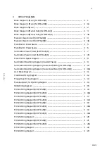
Block Diagram 1 (Main) (for DFD-2S/8)  ............................................................................  C

Block Diagram 1 (Main) (for DFD-2D/8)  ...........................................................................  C

1A 

Block Diagram 2 (Main)  .......................................................................................................  C

Block Diagram 3 (Main & Sub) (for DFD-2S/8)  ................................................................  C

Block Diagram 3 (Main & Sub) (for DFD-2D/8)  ...............................................................  C

3A 

Main AC Power Circuit (for DFD-2S/8)  .............................................................................  C

Main AC Power Circuit (for DFD-2D/8)  .............................................................................  C

4A 

Main Box AC Power Source  .................................................................................................  C

Main Box DC Power Source  .................................................................................................  C

Sub Control Power Circuit (for DFD-2S/8)  ........................................................................  C

Sub Control Power Circuit (for DFD-2D/8)  .......................................................................  C

7A 

Main Control Signal Diagram  .............................................................................................  C

Sub Control Box Wiring Diagram (Y-axis AC Servo)  ......................................................  C

Sub Control Box Wiring Diagram (Y-axis Pulse Motor) (for DFD-2S/8)  ......................  C

10 

Sub Control Box Wiring Diagram (Y-axis Pulse Motor) (for DFD-2D/8)  .....................  C

10A 

ALU Block Diagram  .............................................................................................................. C

11 

Hard Disk Wiring Diagram  .................................................................................................  C

12 

Floppy Disk Wiring Diagram  ..............................................................................................  C

13 

Main-Sub/ALU (S I O) Wiring Diagram  ............................................................................  C

14 

SI/O Wiring Diagram  ............................................................................................................ C

15 

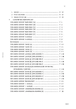
MCN1 Wiring Diagram (for DFD-2S/8)  .............................................................................  C

16 

  MCN1 Wiring Diagram (for DFD-2D/8)  ............................................................................  C

16A 

MCN2 Wiring Diagram (for DFD-2S/8)  .............................................................................  C

17 

  MCN2 Wiring Diagram (for DFD-2D/8)  ............................................................................  C

17A 

MCN3 Wiring Diagram (for DFD-2S/8)  .............................................................................  C

18 

  MCN3 Wiring Diagram (for DFD-2D/8)  ............................................................................  C

18A 

MCN4 Wiring Diagram (for DFD-2S/8)  .............................................................................  C

19 

  MCN4 Wiring Diagram (for DFD-2D/8)  ............................................................................  C

19A 

MCN5 Wiring Diagram  ........................................................................................................  C

20 

MCN6 Wiring Diagram (for DFD-2S/8)  .............................................................................  C

21 

  MCN6 Wiring Diagram (for DFD-2D/8)  ............................................................................  C

21A 

MCN7 Wiring Diagram  ........................................................................................................  C

22 

MCN9 Wiring Diagram  ........................................................................................................  C

23 

Summary of Contents for DFD-2D/8

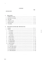
Page 1: ... STRUCTURAL SECTIONS AND THEIR FUNCTIONS CIRCUIT DIAGRAM PRINCIPLES OF OPERATION CHECKING PROCEDURES FOR TROUBLESHOOTING ILLUSTRATION AND PARTS LIST MAINTENANCE AND REGULAR INSPECTIONS ACCESSORIES BLADE BREAKAGE DETECTOR A B C D E F G J H ...

Page 2: ...RUCTURAL SECTIONS AND THEIR FUNCTIONS I Structures B 1 II Functions B 2 1 X axis Section B 2 2 Y axis Section B 3 3 Z axis Section B 4 4 θ axis Section B 6 5 Spinner Section B 9 6 Elevator Section B 10 7 Transfer Section B 12 8 Microscope Section B 13 9 Main Body Section B 18 10 Electrical System B 20 1 Construction B 20 2 Power Supply Section B 24 3 Main Control Section B 32 4 Sub control Section...

Page 3: ...ontrol Box Wiring Diagram Y axis Pulse Motor for DFD 2S 8 C 10 Sub Control Box Wiring Diagram Y axis Pulse Motor for DFD 2D 8 C 10A ALU Block Diagram C 11 Hard Disk Wiring Diagram C 12 Floppy Disk Wiring Diagram C 13 Main Sub ALU S I O Wiring Diagram C 14 SI O Wiring Diagram C 15 MCN1 Wiring Diagram for DFD 2S 8 C 16 MCN1 Wiring Diagram for DFD 2D 8 C 16A MCN2 Wiring Diagram for DFD 2S 8 C 17 MCN2...

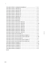
Page 4: ... 8 C 30A SCN7 Wiring Diagram C 31 Outside Relay P C B Circuit Diagram C 32 Set Up P C B Circuit Diagram C 33 PCB Axis C 34 Signal Tower I F P C B Circuit Diagram C 35 Spinner Control P C B Circuit Diagram C 36 Spinner Circuit Diagram C 37 D PRINCIPLES OF OPERATION I Linear Scale D 1 1 Main Components D 2 2 Block Diagram D 3 3 Principles D 4 4 Scale Specifications D 5 E TROUBLESHOOTING GUIDE I Spin...

Page 5: ...DED VIEW OF Y AXIS D F 13 EXPLODED VIEW OF y AXIS A DFD 2D 8 ONLY F 13A EXPLODED VIEW OF y AXIS B DFD 2D 8 ONLY F 13B EXPLODED VIEW OF Z AXIS A DFD 2S 8 ONLY F 14 EXPLODED VIEW OF Z AXIS B DFD 2S 8 ONLY F 14A EXPLODED VIEW OF Z AXIS C DFD 2S 8 ONLY F 14B EXPLODED VIEW OF Z AXIS D BLADE BREAKAGE DETECTOR DFD 2S 8 ONLY OPTION F 14C EXPLODED VIEW OF Z AXIS E DFD 2D 8 ONLY F 15 EXPLODED VIEW OF Z AXIS...

Page 6: ...ING C F 32 EXPLODED VIEW OF PNEUMATIC PIPING D F 33 EXPLODED VIEW OF PNEUMATIC PIPING E F 34 EXPLODED VIEW OF PNEUMATIC PIPING F F 35 EXPLODED VIEW OF PNEUMATIC PIPING G F 36 EXPLODED VIEW OF PNEUMATIC PIPING H F 37 EXPLODED VIEW OF WATER PIPING A F 38 EXPLODED VIEW OF WATER PIPING B DFD 2S 8 ONLY F 39 EXPLODED VIEW OF WATER PIPING C DFD 2D 8 ONLY F 39A EXPLODED VIEW OF WATER PIPING D F 40 EXPLODE...

Page 7: ...AL I Construction J 1 1 Components J 1 II Installation J 4 1 Detection Unit Mounting Position Component in Section I J 4 2 Photo amplifier Mounting Position Component in Section I J 4 III Fiber Installation J 5 IV Connection J 8 V Operating Procedures J 9 1 Preparation for Power ON J 9 2 Power ON J 9 3 Adjustment J 9 4 Idling J 10 5 Breakage Detection Function Activation and Reset J 11 6 Total Los...

Page 8: ...INTRODUCTION D F D 2 S 8 ...

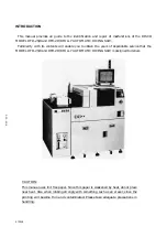
Page 9: ...ble you to obtain the years of dependable service that the MODEL DFD 2S 8 and DFD 2D 8 FULLY AUTOMATIC DICING SAW is designed to deliver CAUTION This manual uses lint free paper Since this paper is weakened by heat do not place near heat Also when rubbing strongly with something such as an eraser since the printing will become thin and contaminated Please take adequate precautions in handling D F ...

Page 10: ...A INSTALLATION D F D 2 S 8 A ...

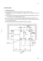
Page 11: ...ure changes abnormally Appropriate temperature is 20 25 1 68 69 5 F 1 8 F and humidity is 55 15 4 Do not use a power source which flucturates frequently Appropriate power is 200V 10 5 Do not use a power source which emits noise Permitted noise is less than 2 000V and its pulse width is less than 500n sec 6 Keep away from where the shock and or sensible vibration are observed Fig A 1 Wall Jack shee...

Page 12: ...nd its dew point is below than 15 5 F 5 Be sure to ground the machine 6 During installation do not load shock and or use excessive force against the machine 7 After installation remove all the hanging fittings and metal fittings for fixing 8 After installation check that all the wiring terminals and piping joints are connected safely IV Installation leveling Level the machine using the jack provid...

Page 13: ...A 3 910228 D F D 2 S 8 Illustration Of Installed Bearing Fig A 2 Fig A 3 Jack bolt Jack sheet Caster Chuck table Level 90mm 3 5 ...

Page 14: ...machine 2 Please verify the coupling connections 3 Be sure to connect the power source cord 4 The power source cord for the monitor is to be connected to a 100V table tap within the machine through the cover 5 Signal cables for the monitor and for the signal lamp are to be linked to each connecter by the cords leading from the machine ...

Page 15: ...2 MSTBH18X12C 3 Spinner duct Duct hose 100 MSTDH100T 10 DI water Blade hose ID15 MSTBH22X15C 4 Spindle exhaust Junron tube8 5 11 N2 Blade hose ID15 MSTBH22X15C 5 Cooling water in Blade hose ID15 MSTBH22X15C 12 Rinse Blade hose ID15 MSTBH22X15C 6 Water for cutting Blade hose ID15 MSTBH22X15C 13 Spinner drainage Blade hose ID32 MSTBH41X32C 7 Air Blade hose ID15 MSTBH22X15C 14 Exhaust drainage spinne...

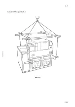
Page 16: ... 7 Put on a hanging fittings for transportation 8 Run a pole through the hanging fitting and raise the machine with a crane 9 Notes for craning Pay attention that ropes etc do not touch the machine Do not shock the machine Do not incline the machine excessively Do not weigh on the cover 10 After raising up the machine all the jack bolts are to be pulled in to the utmost If they remain below the ca...

Page 17: ...A 7 910228 D F D 2 S 8 Illustration Of Transport Method Fig A 5 ...

Page 18: ...B STRUCTURAL SECTIONS AND THEIR FUNCTIONS B D F D 2 S 8 ...

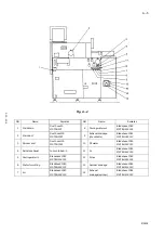
Page 19: ... 8 consists of the X axis Y axis y axis only for the DFD 2D 8 Z axis θ axis spinner elevator transfer microscope main body and electrical sections Elevator section Spinner section Transfer section Z axis section Fig B 1 θ axis section Main body section Electrical section X axis section Y axis section ...

Page 20: ... performs work transport rightward leftward feed for alignment and reciprocating cutting movements 2 Leadscrew Section This section moves the slide table by means of the ball bearing leadscrew coupled direct to the AC servomotor 3 Cover Section The splash cover bellows cover and water drain duct are provided to discharge the cutting water out from the machine protecting the mechanism against water...

Page 21: ... water 3 Leadscrew Section The ball bearing leadscrew coupled direct to the AC servomotor is used in combination with straight rails to move a slide base on which the Y y only for the DFD 2D 8 and Z axis sections and microscope are mounted The slide base is moved for cutting positioning purposes 4 y axis Section only for the DFD 2D 8 The ball bearing leadscrew coupled direct to the pulse motor is ...

Page 22: ... F D 2 S 8 3 Z axis section DFD 2S 8 The Z axis section consists of the Z axis 1 spindle holder 2 and blade damage detection option 3 section Fig B 4 Z axis Blade breakage detector section Spindle holder Z section ...

Page 23: ...2S 8 The Z axis section consists of the Z1 axis 1 Z2 axis 2 spindle holder Z1 3 spindle holder Z2 4 and blade damage detection 5 section Fig B 4A Z1 axis Z2 axis Spindle holder Z1 section Spindle holder Z2 section Blade breakage detector section ...

Page 24: ... that Z axis section movement is converted to spindle vertical motion 3 Blade damage detection section option The employed sensor monitors the blade condition performs signal processing and issues the blade damage alarm The sensor is mounted on the wheel cover The wheel cover performs the functions of both the blade rotation section safety cover and cutting water supply nozzle CAUTION When rotatin...

Page 25: ...lder Z2 section Spindle 2 and its holder are provided in this section Spindle 2 which is a high frequency motor air spindle rotates at high speed with a blade attached to its end The holder secures spindle 2 so that Z2 axis section movement is converted to spindle 2 vertical motion 5 Blade damage detection section The employed sensor monitors the blade condition performs signal processing and issu...

Page 26: ...r to achieve angular position indexing 2 Chuck Table Section The 3 to 8 inch diameter wafer chuck tables are used to provide vacuum to chuck wafers The chuck table must be replaced as required to suit the employed wafer size The frame clamp fixes various tape frames to support wafer chucking operations The splash cover is provided to prevent the cutting water from entering the mechanical sections ...

Page 27: ...To install a chuck table be sure to turn it into the base straight to avoid damage to the threads Before chuck table installation remove any scratches or burrs from the chuck table lower surface and base upper surface with fine oil stone and wipe any remaining dirt off Fig B 6 CHUCK TABLE ASSY PARTS No 3INCH MADPR002 4INCH MADPR003 5INCH MADPR004 6INCH MADPR005 8INCH MADPR006 CHUCK TABLE BASE ...

Page 28: ...B 8 920610 D F D 2 S 8 Frame Clamp Adjustment Procedure Adjust the frame clamp mounting position as required to match the employed frame type Fig B 7 DTF2 8 1 position DTF2 6 1 position DTF2 6 position ...

Page 29: ...riven so that they move above the table As they move above the table they jet out a cleaning solution or drying nitrogen for wafer cleaning or drying purposes 3 Rotary Section Tables for 3 to 6 inch or 8 inch diameter wafers are used to chuck wafers by means of a vacuum The AC servomotor rotates the selected table to carry out cleaning drying or loading positioning Table Changeover Two tables are ...

Page 30: ...d piping 3 Fig B 9 1 Elevator A pulse motor is operated in conjunction with a ball bearing leadscrew to move the cassette mounted table up and down 2 Electrical System Elevator and transfer motor drivers controller and power supply are included in the electrical system Elevator Electrical system Piping section ...

Page 31: ...fer and spinner valves and pumps are contained in the piping system Elevator Table Cassette Block Adjustment Adjust the block mounting position as required to match the employed cassette Fig B 10 2 8 cassette 2 6 1 2 6 1A cassette 2 6 2 6A cassette ...

Page 32: ...ft by the pulse motor and ball screw so that the tape frame is clamped mechanically This arm is exclusively used for uncut but cleaned wafers 2 Pud arm Section The arm in this section is moved up down front and rear by the employed air cylinder so that the tape frame is clamped by means of a vacuum This arm is exclusively used for uncleaned wafers Finger arm section Pud arm section ...

Page 33: ...icro macro function is provided to permit changeover between large and small magnifications 2 Accessories A micrometer type fine adjustment mechanism is used to align the microscope center line with the blade position An optical fiber cord is provided to derive illumination light from the light source 3 Microscope Adjustment Procedure 1 CCD Camera Angle Adjustment Microscope Focus adjust Pulse mot...

Page 34: ...tern attached wafer and make focus adjustment Effect magnification changeover by function key activation to call up the macro screen Loosen the intermediate lens assembly x1 3 by turning it counterclockwise Stop the lens assembly in the position at which sharp focus is achieved Change the intermediate lens forward backward position by the amount equivalent to the distance between the original lens...

Page 35: ...ertical adjustment so that the hairline coincides with the street center Loosen three of the four screws and slide the plate as required to make proper adjustment To make hairline and street angle adjustment adjust the pull or push screw as appropriate After completion of adjustment fully tighten the screws Fig B 15 Fig B 16 4 Hairline Monitor Adjustment Make adjustment so that the ALU output targ...

Page 36: ...board mounted DIP switches as indicated below Fig B 19 After completion of adjustment place the PC board back into its original position reconnect the connector and turn ON the ALU switch Repeat steps through until the target wimdow aligns with the hairline CRT Hairline ALU Target Window P C B EAUA 1368 DSW1 Vertical Direction Each time switch 1 is turned ON the target window moves approximately 1...

Page 37: ...pe Blow Adjustment Fig B 20 Microscope Scope covering Remove the scope covering Make sure that the air blow off opening faces toward the center Appropriate direction of air blow off Microscope Top view of the microscope Front Rear ...

Page 38: ...the base for the main mechanical system Equipped with a level adjusting jack and casters 2 Electrical System Box Motor drivers and controllers are contained in this box Rails are provided so as to facilitate box insertion and extraction 3 Drain This drain is used to draw the waste cutting water out from the machine Piping section Wiring section Drain section Base section Electrical system box ...

Page 39: ...S 8 4 Piping Section X Y Z and θ axis microscope main body and cutting water system valves are assembled in this section This section also has air and water supply ports 5 Wiring section Wire clamping brackets are provided ...

Page 40: ...rol section is divided into a 68000 CPU control RACK unit a monitor synthesis unit a hard disk unit a floppy disk unit an ALU unit a focus motor driver a setup interface and regulated DC power supplies for all units Sub control Section The sub control section of the DFD 2S 8 or DFD 2D 8 consists of control boards for the two axis AC servo motor and three axis stepping motor or five axis stepping m...

Reviews: