background image


INSTRUCTION MANUAL 


DX2400L1 HF LINEAR AMPLIFIER 

“The Prometheus” 


PATENT PENDING 

DX2400L1INS1 Revision 1.0 10/2006 


Dishtronix, Inc. 

2497 ROAD 55 

Bellefontaine, Ohio 43311 USA 

TEL +1 937 292 7981 

http://www.dishtronix.com


info@dishtronix.com


© 2006 by Dishtronix, Inc. All Rights Reserved. 

D

ishtronix

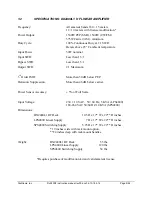
Summary of Contents for DX2400L1

Page 1: ...FIER The Prometheus PATENT PENDING DX2400L1INS1 Revision 1 0 10 2006 Dishtronix Inc 2497 ROAD 55 Bellefontaine Ohio 43311 USA TEL 1 937 292 7981 http www dishtronix com info dishtronix com 2006 by Dis...

Page 2: ...Copyright 2006 by Dishtronix Inc ALL RIGHTS RESERVED No part of this document may be copied reproduced transmitted or used without the express written consent of Dishtronix Inc Information theory tec...

Page 3: ...Dishtronix will be able to continue its pioneering efforts in the HF solid state high power arena I know there are some other solid state units coming along Please set my unit side by side with theirs...

Page 4: ...Full Break In QSK 14 2 6 Semiautomatic Break In 14 2 7 PTT QSK Operation 15 3 OPERATION 19 3 1 Front Panel Controls 21 3 2 Rear Panel Controls and Connectors 22 3 3 Connector Pin Definitions 25 3 4 12...

Page 5: ...Interface Line Bias 35 3 11 03 Setting Remote Interface Power Options 35 4 THEORY OF OPERATION 37 4 1 Block Diagram 39 4 2 Amplifier Circuitry Overview 39 5 0 SERVICE 41 5 1 Maintenance 42 5 1 1 Opti...

Page 6: ...Dishtronix Inc Dx2400l1 instruction manual rev00 doc 06 10 18 5 14 Page 6 44 This page left intentionally blank...

Page 7: ...to man In retaliation Zeus the King of the Gods chained him to a rock where every day an eagle ate his liver and each night it magically grew back Three thousand years later this Prometheus puts legal...

Page 8: ...rotection circuit Over temperature warning and shutdown protection Over under voltage lockout protection Overdrive protection Hardware failure protection combiner balance PIN T R failure Digital bargr...

Page 9: ...Output SWR 2 1 Maximum 3rd Order IMD More than 30 dB below PEP Harmonic Suppression More than 46 dB below carrier Power Sensor Accuracy 5 of Full Scale Input Voltage 230 10 VAC 50 60 Hz 5 KVA LPS4800...

Page 10: ...ve been specifically designed by Dishtronix to work with the DX2400L1 RF Amplifier Dishtronix Amplifier to RS232 Computer Interface Dishtronix Fan Filter Kit Dishtronix DX2400L1 Amplifier to Yaesu Ban...

Page 11: ...Dishtronix Inc Dx2400l1 instruction manual rev00 doc 06 10 18 5 14 Page 11 44 2 INSTALLATION...

Page 12: ...e braids Two inch slit copper rolls are available through various sources that can be used in place of the braid Consult the ARRL Radio Amateurs Handbook and the National Electric Code Handbook for in...

Page 13: ...AC power line to the AC mains supply 4 Connect a voltmeter across the HV supply pins Refer to power supply manual 5 Turn the front panel switch on The amplifier front panel lights should come on 6 Pr...

Page 14: ...activated regardless of the exciter mode The transceiver signals the amplifier to place itself in transmit mode through the exciter s KEY OUT line which is connected to the amplifier KEY IN connector...

Page 15: ...AM or FM modes deactivate the amplifier front panel QSK mode and T R operation will be as described in the SEMI AUTOMATIC BREAKIN paragraph above When CW operation is desired activate the front panel...

Page 16: ...Dishtronix Inc Dx2400l1 instruction manual rev00 doc 06 10 18 5 14 Page 16 44 Figure 1 DX2400 Typical Installation with QSK Full Loop Keying...

Page 17: ...Dishtronix Inc Dx2400l1 instruction manual rev00 doc 06 10 18 5 14 Page 17 44 Figure 2 Typical Installation for Non QSK Keying Vintage Transceiver...

Page 18: ...Dishtronix Inc Dx2400l1 instruction manual rev00 doc 06 10 18 5 14 Page 18 44 Figure 3 QSK Installation using Non QSK Transceiver and External Keyer...

Page 19: ...Dishtronix Inc Dx2400l1 instruction manual rev00 doc 06 10 18 5 14 Page 19 44 3 OPERATION...

Page 20: ...Dishtronix Inc Dx2400l1 instruction manual rev00 doc 06 10 18 5 14 Page 20 44 Figure 4 Front Panel Features...

Page 21: ...temperature E ALC Indicator Illuminates as the generated ALC voltage begins to significantly depart from 0 volts negative F QSK Indicator Illuminated when Full Loop Keying mode is selected by QSK K s...

Page 22: ...dB attenuator C TUN ADJ this control is not used and is reserved for future expansion of the DX2400L1 D ALC ADJ this control is used to set the ALC feedback level to the exciter Refer to Section 3 9 t...

Page 23: ...is connector has slightly less reflection than ANTENNA 4 so it should be used for the second lowest frequency antenna typically the 80m 40m parallel resonant dipole or inverted vee antenna P ANTENNA 2...

Page 24: ...Dishtronix Inc Dx2400l1 instruction manual rev00 doc 06 10 18 5 14 Page 24 44 Figure 5 Rear Panel Controls and Connectors...

Page 25: ...turn Module 2 Supply Return Module 2 Supply Return Module 1 Supply 72V Source Module 1 Supply 72V Source Module 2 Supply 72V Source Module 2 Supply 72V Source BAND DATA Mini DIN Female 1 2 3 4 5 6 7 8...

Page 26: ...er is switched on As shipped from the factory the default power up condition for the amplifier is the bypass mode The default condition can be toggled to power up by entering the programming mode See...

Page 27: ...f selecting the proper amplifier band 1 Automatically via rear panel BAND DATA connector 2 From transceiver or PC via the RS485 422 interface rear panel DATA connector 3 Manually from front panel BAND...

Page 28: ...n is strongly discouraged The following chart details the BAND DATA lines and corresponding amplifier band selection BAND BDATA_D BDATA_C BDATA_B BDATA_A 160m 0V 0V 0V 5V 80m 0V 0V 5V 0V 60 40m 0V 0V...

Page 29: ...icating that it is generating ALC voltage The illumination begins somewhere in the range of 0 7 to 1 0 Volt of ALC 3 9 2 ALC SWR Foldback Note that the ALC system is designed to generate significant A...

Page 30: ...ounding Try using a shielded cable with one end of the shield grounded to the amplifier or the transmitter but not both Try routing the cable away from antenna and other leads or wrap it on ferrite co...

Page 31: ...voice peaks the front panel OVERDRIVE indicator will flash and the amplifier will enunciate with an audio chirp starting at about 2 KW internally adjustable Should the amplifier be severely overdriven...

Page 32: ...een carefully designed and has a large cooling margin built in but under severe cases of high duty cycle operation for example FM in a hot environment or should the cooling fans or exhaust slots be ob...

Page 33: ...ault Conditions The faults fall into two categories operational faults and hardware faults Operational soft faults are triggered by external events such as high SWR overdrive over temperature etc Oper...

Page 34: ...magnetic fields radiated by the conductors oppose each other and cancel Hence the transmission line is balanced and radiates very little energy Since the transmission line is balanced external electri...

Page 35: ...d from the rear panel 12V supply which is normally connected to the 12V output of the transceiver AUX 12V jack It is possible to supply power to the remote interface from the 12V jack default from the...

Page 36: ...rev00 doc 06 10 18 5 14 Page 36 44 Note that a wall wart type of DC transformer may be useful to supply power to the interfaces in place of the transceiver accessory 12V power supply Simply connect t...

Page 37: ...Dishtronix Inc Dx2400l1 instruction manual rev00 doc 06 10 18 5 14 Page 37 44 4 THEORY OF OPERATION...

Page 38: ...Dishtronix Inc Dx2400l1 instruction manual rev00 doc 06 10 18 5 14 Page 38 44 Figure 7 DX2400L1 Block Diagram...

Page 39: ...down from the input level Each of these signals are used to drive identical push pull broadband power modules operating at 72V Each RF power module is matched for gain within a fraction of a dB by an...

Page 40: ...it Finally the antenna selector unit mounted on the rear panel selects 1 of 4 antennas under microprocessor control The signal from the power sensor is passed to the Amplifier Control Assembly where t...

Page 41: ...Dishtronix Inc Dx2400l1 instruction manual rev00 doc 06 10 18 5 14 Page 41 44 5 SERVICE...

Page 42: ...ewhat and also muffle the fan noise slightly To clean the filters simply pry the cover off of the fan and wash the filters in a mild detergent solution Let the filter elements air dry before reinstall...

Page 43: ...oblem Also include a brief description of the service you wish performed Be certain to include your name address telephone number email address and fax number if applicable Pack the unit in the origin...

Page 44: ...Dishtronix Inc Dx2400l1 instruction manual rev00 doc 06 10 18 5 14 Page 44 44 NOTES...

Reviews: