


Dishtronix, Inc.
Dx2400l1 instruction manual rev00.doc 06-10-18 5.14
Page 14/44
2.4
Mounting RF Deck on Top of Power Supply
The RF deck may be mounted on top of the Power Supply if desired. There are two small dowel
pins included in the package. Fit two of these pins into the top center hole of two of the four
metal feet mounted on top of the power supply. It is best to place one pin diagonally from the
other. Next, with a helper, lift the RF deck and place carefully over the power supply, guiding
the feet of the RF deck over the pins so that the RF deck drops into place and will not slide off of
the power supply. Now you may attach the two HV DC power cables, the control interconnect
cable, the ground straps and other interconnecting lines to the exciter such as ALC, PTT, etc.
Refer to the following discussion of Loop Keying and Break In Operation to determine correct
installation for your particular transceiver.
2.5
Full Break In QSK
{Operation with Modern Transceivers that use Full Loop Keying}
Some modern transceivers feature full loop keying circuitry. The idea behind full loop keying is
to correctly sequence the external power amplifier so that it is switched in line BEFORE the
transmitter is keyed, and remains in line a short time AFTER the transmitter is unkeyed.
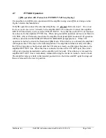
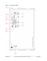
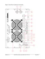
Figure 1 shows correct installation with a full loop keying transceiver. With this type of
installation there is no separate PTT line to the amplifier, so the amplifier front panel QSK key
control should always be activated regardless of the exciter mode. The transceiver signals the
amplifier to place itself in transmit mode through the exciter’s KEY OUT line which is connected
to the amplifier KEY IN connector. When the amplifier is placed in QSK mode, whenever the
transceiver pulls this line to ground the amplifier will activate its internal antenna changeover
relays. When the amplifier is ready to transmit, it will signal the exciter to produce RF by pulling
the amplifier KEY OUT line to ground. This line is connected to the exciter KEY IN line. When
the key is released, the exciter should quit producing RF and release the exciter KEY IN line.
After a brief pause to insure no RF is flowing, the amplifier changes back to receive mode.
2.6
Semiautomatic Break In
{Operation with Traditional Transceivers using PTT (not Full Loop) Keying}
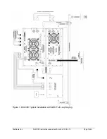
It is possible to operate the exciter in a more traditional mode of operation where the transceiver
simply activates the amplifier change over relay. Figure 2 details installation of the amplifier
with vintage or non-QSK transceivers. For this installation the exciter PTT OUT line simply
connects to the amplifier PTT IN jack. The front panel QSK operation must be deactivated.
When the transmitter is keyed, it signals the amplifier to come on line by pulling the PTT line to
ground. The amplifier switched the antenna to the antenna output first to insure that the amplifier
will not operate into an open circuit or hot switch the output relay. Once the antenna relay is
activated, the amplifier switches the exciter output to the amplifier input. When the PTT line is
released, the amplifier input relay is released, and then the amplifier antenna relay is released.
Summary of Contents for DX2400L1
Page 11: ...Dishtronix Inc Dx2400l1 instruction manual rev00 doc 06 10 18 5 14 Page 11 44 2 INSTALLATION...
Page 19: ...Dishtronix Inc Dx2400l1 instruction manual rev00 doc 06 10 18 5 14 Page 19 44 3 OPERATION...
Page 41: ...Dishtronix Inc Dx2400l1 instruction manual rev00 doc 06 10 18 5 14 Page 41 44 5 SERVICE...
Page 44: ...Dishtronix Inc Dx2400l1 instruction manual rev00 doc 06 10 18 5 14 Page 44 44 NOTES...


