


Dishtronix, Inc.
Dx2400l1 instruction manual rev00.doc 06-10-18 5.14
Page 21/44
3.1
Front Panel Controls
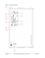
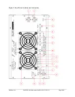
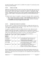
Figure 4 details the front panel controls.
A.
Power Switch – Activates internal low voltage supply for metering, logic and
communications circuits.
B.
Antenna Select Indicators – Indicates which antenna is currently selected by the ANT
switch (I).
C.
Bypass Indicator – Indicates that amplifier is bypassed in the standby mode and that the
high voltage supply has been disabled. Activated by the BYPASS (J) key or when a fault
condition places the amplifier in protection mode. Blinks while high voltage supply
charges up. May blink in conjunction with Error Status Indicators (D) for fault diagnosis
readout.
D.
Error Status Indicators – Indicates either individual conditions if not blinking, or other
faults according to Chart in Section 3.10 if blinking.
1. SWR Indicator – Active if reflected power exceeds safe level.
2. DRIVE Indicator – Blinks whenever input power exceeds recommended drive level
regardless of internal attenuator settings. Continuously on as a latched fault condition
whenever drive exceeds maximum safe input drive level.
Note – both indicators are latched on until the unit cools when over temperature.
E.
ALC Indicator - Illuminates as the generated ALC voltage begins to significantly depart
from 0 volts negative.
F.
QSK Indicator – Illuminated when Full Loop Keying mode is selected by QSK (K)
switch.
G.
AUTO Indicator – Illuminated whenever external rear panel BAND DATA signals are
present, or when the frequency counter band selection mode is selected by the BAND (L)
switch control.
H.
BAND Select Indicators - Indicates which low pass filter has been selected by the
external rear panel BAND DATA signals, if present, or by the internal frequency
measuring circuit, if activated, or by the manual selection of the BAND (L) switch.
I.
ANT Select Switch – used to select rear panel antenna for each band. Note that the
selection is automatically stored for each setting of the BAND switch. To select a
different antenna depress the switch and cycle through the antennas by watching the
antenna select indicator (B)
J.
BYPASS Switch – used to toggle the amplifier in or out of line as indicated by the
BYPASS Indicator (C). Press this switch to clear a fault condition such as SWR or Drive
and place the amplifier back on line AFTER the cause of the fault has been determined
and corrected.
K.
QSK Loop Keying Select Switch – used to select FULL LOOP KEYING, with amplifier
transceive triggered by the back panel KEY IN jack, or PTT KEYING with the amplifier
transceiver triggered by the back panel PTT IN jack.
Summary of Contents for DX2400L1
Page 11: ...Dishtronix Inc Dx2400l1 instruction manual rev00 doc 06 10 18 5 14 Page 11 44 2 INSTALLATION...
Page 19: ...Dishtronix Inc Dx2400l1 instruction manual rev00 doc 06 10 18 5 14 Page 19 44 3 OPERATION...
Page 41: ...Dishtronix Inc Dx2400l1 instruction manual rev00 doc 06 10 18 5 14 Page 41 44 5 SERVICE...
Page 44: ...Dishtronix Inc Dx2400l1 instruction manual rev00 doc 06 10 18 5 14 Page 44 44 NOTES...


