


Dishtronix, Inc.
Dx2400l1 instruction manual rev00.doc 06-10-18 5.14
Page 22/44
L.
BAND Select Switch – Used to manually select appropriate filter if no external signals
are present on the rear panel BAND DATA connector, or used to select the internal
frequency measuring circuit to automatically sample the incoming signal and select the
correct filter when no BAND DATA is available from the transceiver. Note that presence
of external BAND DATA overrides operation of the BAND switch and that frequency
counter and manual band selection is not possible. For manual band selection depress the
BAND select key and scroll through the bands as displayed on the front panel BAND
Select Indicators (H). For internal frequency measuring mode depress and hold the BAND
select Key for approximately 5 seconds until the front panel AUTO Band Indicator (G)
illuminates. Frequency counter mode will be saved and active at power on until it is reset
by the user.
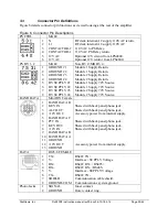
3.2
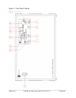
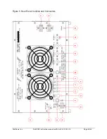
Rear Panel Controls and Connectors
Figure 5 details the rear panel controls and connectors.
A.
Cooling Fans – move cooling air through the cabinet. May be externally replaced by
unplugging the supply cable from the rear panel FAN connector (M). Do not obstruct
airflow to the fans!
B.
TRANSMITTER Input – RF input to the exciter or transceiver. Do not exceed 100W on
this connector without activating the internal 3dB attenuator.
C.
TUN ADJ – this control is not used and is reserved for future expansion of the
DX2400L1.
D.
ALC ADJ - this control is used to set the ALC feedback level to the exciter. Refer to
Section 3.9 to adjust this control.
E.
PS CTRL - this connector caries control signals and 110VAC power for the internal low
voltage control from the LPS4800 or SPS4800 Power Supply. See section 3.3 for pin
information.
F.
DATA Connector - this connector caries signals to interface the amplifier computer to
external RS485 or RS422 interfaces. See section 3.3 for pin information.
G.
BAND DATA Connector - this connector caries BAND data signals for automatic band
switching from the exciter. ALC and Keying signals are also duplicated on this connector.
See section 3.3 for pin information.
H.
+12V IN Connector - this connector is typically connected to the exciter sw12V
accessory output connector. This voltage is used to power the exciter side of the optically
isolated interface functions (BAND DATA, PTT, KEY IN, KEY OUT, DATA). When
+12V is applied, the amplifier front panel switch is bypassed and the amplifier low
voltage and metering circuits are automatically switched. See section 3.4 and 3.5 for more
information and configuration options.
I.
ALC OUT – this connector supplies the negative ALC feedback voltage to the exciter.
J.
KEY IN – this connector is used by the exciter to signal the amplifier to enter transmit
mode when front panel QSK mode (FULL LOOP KEYING) is selected. If the front panel
QSK mode is not selected, this connector has no effect on amplifier operation.
Summary of Contents for DX2400L1
Page 11: ...Dishtronix Inc Dx2400l1 instruction manual rev00 doc 06 10 18 5 14 Page 11 44 2 INSTALLATION...
Page 19: ...Dishtronix Inc Dx2400l1 instruction manual rev00 doc 06 10 18 5 14 Page 19 44 3 OPERATION...
Page 41: ...Dishtronix Inc Dx2400l1 instruction manual rev00 doc 06 10 18 5 14 Page 41 44 5 SERVICE...
Page 44: ...Dishtronix Inc Dx2400l1 instruction manual rev00 doc 06 10 18 5 14 Page 44 44 NOTES...


