


Dishtronix, Inc.
Dx2400l1 instruction manual rev00.doc 06-10-18 5.14
Page 23/44
K.
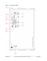
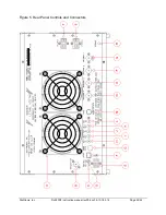
KEY OUT – this connector is used by the amplifier to signal the exciter to begin
transmitting once the amplifier is in transmit mode when front panel QSK mode (FULL
LOOP KEYING) is selected. If the front panel QSK mode is not selected, this connector
has no effect on amplifier operation.
L.
PTT IN - this connector is used to place the amplifier in transmit mode for traditional or
vintage transmitters that do not support full loop keying. Grounding this pin will place the
amplifier in transmit mode when the front panel QSK mode is not selected. If QSK mode
is selected, this connector is ignored and has no function or effect on amplifier operation.
M.
FANS - this connector carries power to the cooling fans. Do not unplug this connector!
N.
ANTENNA 4 – this connector is selected by the front panel ANT switch. This connector
has the poorest reflection at the high end of the band, so it should be used for the lowest
frequency antenna, typically the 160m receiving loop.
O.
ANTENNA 3 – this connector is selected by the front panel ANT switch. This connector
has slightly less reflection than ANTENNA 4, so it should be used for the second lowest
frequency antenna, typically the 80m/40m parallel resonant dipole or inverted-vee
antenna.
P.
ANTENNA 2 - this connector is selected by the front panel ANT switch. This connector
has slightly less reflection than ANTENNA 3, so it should be used for the third lowest
frequency antenna, typically the vertical 40m-10m vertical antenna.
Q.
ANTENNA 1 - this connector is selected by the front panel ANT switch. This connector
has the best match of all antenna connectors, so it should be used for the highest
frequency antenna, typically the 20m-10m multiband beam antenna. NOTE: When the
amplifier is powered off, this antenna is jack is connected straight through to the rear
panel TRANSMITTER INPUT Jack (B) Hence the transceiver will use this antenna if the
amplifier unit is not powered.
R.
GROUND - this terminal is for grounding the equipment to the station ground. Do not
daisy chain equipment ground together. See the Installation section for correct grounding
procedures.
S.
PS HV1 – This connector carries the high voltage DC to internal power modules #1 and
#2 from the LPS4800 or SPS4800 Power Supply.
T.
PS HV2 – This connector carries the high voltage DC to internal power modules #3 and
#4 from the LPS4800 or SPS4800 Power Supply.
Summary of Contents for DX2400L1
Page 11: ...Dishtronix Inc Dx2400l1 instruction manual rev00 doc 06 10 18 5 14 Page 11 44 2 INSTALLATION...
Page 19: ...Dishtronix Inc Dx2400l1 instruction manual rev00 doc 06 10 18 5 14 Page 19 44 3 OPERATION...
Page 41: ...Dishtronix Inc Dx2400l1 instruction manual rev00 doc 06 10 18 5 14 Page 41 44 5 SERVICE...
Page 44: ...Dishtronix Inc Dx2400l1 instruction manual rev00 doc 06 10 18 5 14 Page 44 44 NOTES...


