


Dishtronix, Inc.
Dx2400l1 instruction manual rev00.doc 06-10-18 5.14
Page 26/44
3.4
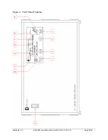
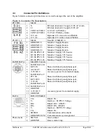
+12V IN Jack
The amplifier is completely optically isolated from the outside world, with the exception of the
ALC line. The amplifier is set at the factory so that power for the BAND DATA jack, as well as
the remote interface is normally supplied from this port. This jack is normally connected to the
trans12V AUX line. Most transceivers switch the +12V AUX line off and on. As
configured at the factory, the amplifier turns on automatically wh12V is present at this
jack. See the Auto Power On discussion section for more details.
3.5
Auto Power On Feature
Wh12V is supplied to the rear panel +12V In jack, the front panel switch is overridden.
The 12V signal activates an optically isolated triac which shorts the power switch to the ON
position. This feature can be disabled by removing the 1K
Ω
resistor R1 on the Logic Power
Supply PCB located behind the front panel. This feature allows the amplifier metering circuits to
power up automatically when the transceiver is switched on.
As shipped from the factory, the default power up condition for the amplifier is the bypass mode.
The default condition can be toggled to power up by entering the programming mode. See the
programming mode section for more details.
3.6 Programming
Mode
The default power up state of the amplifier can be changed from the programming mode.
•
To enter the programming mode, turn off the transceiver and amplifier front panel switch.
•
Depress the ANT and BAND keys simultaneously, and turn the amplifier power switch to
ON
•
To enable or disable a feature, depress the appropriate toggle key according to the chart
below.
•
To exit the programming mode, turn the amplifier front panel switch off.
•
Allow a short pause, and reactivate the amplifier by either the transceiver remote on or the
front panel switch. The amplifier should come up in the new desired state.
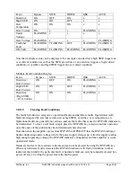
The following chart details different setting options for the program mode:
Feature
Display LED
Illuminated
Extinguished
Toggle Key
Power On State
BYPASS
Standby*
Operate
BYPASS
QSK state
QSK
Loop keying
PTT keying*
QSK
Interface mode
BAND AUTO
RS422*
RS485
BAND
200W attenuator DRIVE
Active
Disabled*
ANT
PIN T/R Enable
SWR
Installed
Bypassed
BAND+QSK
* denotes (default) settings as shipped from factory.
Summary of Contents for DX2400L1
Page 11: ...Dishtronix Inc Dx2400l1 instruction manual rev00 doc 06 10 18 5 14 Page 11 44 2 INSTALLATION...
Page 19: ...Dishtronix Inc Dx2400l1 instruction manual rev00 doc 06 10 18 5 14 Page 19 44 3 OPERATION...
Page 41: ...Dishtronix Inc Dx2400l1 instruction manual rev00 doc 06 10 18 5 14 Page 41 44 5 SERVICE...
Page 44: ...Dishtronix Inc Dx2400l1 instruction manual rev00 doc 06 10 18 5 14 Page 44 44 NOTES...


