


Dishtronix, Inc.
Dx2400l1 instruction manual rev00.doc 06-10-18 5.14
Page 29/44
modern solid state age, and in fact is an inconvenient cost adding feature. . The only reason for
negative ALC is for industry compatibility.
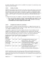
ALC is a difficult feature to implement on an amplifier designed to be used with many different
transceivers. A problem exists because there is no standardized ALC voltage level or formula
between different transceiver manufacturers. Some manufacturers even have different ALC levels
on different model transceivers! For example the ALC on a Kenwood TS-950SDX was found to
be in the 0 to -7 V range, while a Kenwood TS570D was measured in the 0 to-9V range. An
Yaesu FT100 was found to be in the 0 to-2.5V range.
Amplifiers manufactured by Dishtronix loosely follow, and Dishtronix proposes all
manufacturers adopt, the following general ALC voltage relationship:
OUT
ALC
P
V
5
1
≅
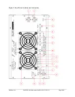
Hence for 1500W output, the output ALC voltage is 7.75 Volts. The ALC ADJ adjustment
potentiometer on the amplifier rear panel shifts this voltage up or down as necessary for your
particular exciter.
3.9.1
ALC Indicator
The front panel ALC indicator illuminates when the amplifier starts to significantly depart from
0V, indicating that it is generating ALC voltage. The illumination begins somewhere in the range
of -0.7 to -1.0 Volt of ALC.
3.9.2
ALC-SWR Foldback
Note that the ALC system is designed to generate significant ALC voltage whenever the reflected
power exceeds approximately 200W (an SWR of about 2.1:1 with 1700W forward and 200W
reflected). The goal is for the ALC to reduce the exciter drive so that the reflected power is
limited to this level, regardless of exciter drive.
WARNING!
Improperly adjusting the ALC when there is significant reflected power may defeat this
SWR-ALC fold back protection feature, posing a risk of damage to your amplifier, should
one of the other protection features (overdrive, over current or SWR limit) fail. The
SWR-ALC fold back circuit is your first line of defense!
3.9.3
ALC Adjustment Procedure
The ALC adjustment procedure follows:
1.
Select an antenna with VSWR < 1.5 on the 14 MHz band or a suitably sized dummy load.
2.
Rotate the amplifier rear panel ALC ADJ control fully counter clockwise (minimum
ALC action).
3.
Set the transceiver to 14 MHz and minimum drive.
4.
Key the transmitter and supply about 10W of power to the amplifier. Note that the
amplifier is outputting power OK. Advance the transceiver drive control slowly. At some
point the ALC front panel indicator should illuminate. Continue increasing transmitter
drive to read about 1500-1600W (or the desired output level) on the wattmeter.
Summary of Contents for DX2400L1
Page 11: ...Dishtronix Inc Dx2400l1 instruction manual rev00 doc 06 10 18 5 14 Page 11 44 2 INSTALLATION...
Page 19: ...Dishtronix Inc Dx2400l1 instruction manual rev00 doc 06 10 18 5 14 Page 19 44 3 OPERATION...
Page 41: ...Dishtronix Inc Dx2400l1 instruction manual rev00 doc 06 10 18 5 14 Page 41 44 5 SERVICE...
Page 44: ...Dishtronix Inc Dx2400l1 instruction manual rev00 doc 06 10 18 5 14 Page 44 44 NOTES...


