


Dishtronix, Inc.
Dx2400l1 instruction manual rev00.doc 06-10-18 5.14
Page 32/44
3.10.5
Power Supply Under Voltage Lockout
If the power supply voltage is marginally low, the amplifier will continue to function normally,
but maximum power output level will be decreased. Some research indicates decreasing the
voltage on the RF transistors extends life and may provide a higher level of fault tolerance for
high SWR events. For example, reducing the power supply voltage from 72 to 60V will reduce
the maximum output level from 2400W to 1600W. 50V operation reduces the power available to
about 1200W. Below 45V (software adjustable), the amplifier assumes the power supply is
defective and activates the under voltage lock out feature, placing the amplifier in the BYPASS
mode and display the appropriate fault code on the front panel.
NOTE – the companion LPS4800 Linear Supply contains 4 internal fuses to the back
panel HV connector. Should any fuse blow, the LPS4800 mains contactor will not
activate, preventing operation of the HV supply. This will activate the DX2400 under
voltage lockout feature with the DX2400 displaying the appropriate fault code. Consult
the LPS4800 Linear Power Supply manual to replace the internal fuse(s).
3.10.6
Over Temperature Protection
Should the amplifier heat exchanger temperature exceed a preset level, the over temperature
protection circuit will activate, placing the amplifier in the BYPASS mode, and display the
appropriate fault code on the front panel. The cooling system of this amplifier has been carefully
designed and has a large cooling margin built in, but under severe cases of high duty cycle
operation, for example FM, in a hot environment, or should the cooling fans or exhaust slots be
obstructed, or should some of the cooling fans fail, the over temperature protection may activate.
Allow the amplifier to cool, check for cooling obstruction and that the fans are operating, and
continue operation. Remember that heat is the enemy of any amplifier. Solid state amplifiers
running Class AB are typically only 50% efficient, so for 1500W of RF output you need to
exhaust 1500W of heat, which is as much heat as a portable room space heater generates!
3.10.7
Combiner Failure Fault
In the event of failure or significant gain reduction of one or more of the RF power modules,
causing a combiner imbalance, the combiner imbalance detector (hardware fault) protection
circuit will activate, placing the amplifier in the BYPASS mode and display the appropriate fault
code on the front panel.
3.10.8
T/R Failure Fault
In the event of failure of the optional PIN diode T/R switch circuit, the T/R fault (hardware fault)
protection circuit will activate, placing the amplifier in the BYPASS mode and display the
appropriate fault code on the front panel. This fault mode is caused when RF is detected flowing
in the transmit path when the unit is trying to switch to receive. Should the fault persist, the PIN
diode T/R circuit board will need service. Note that for emergency operation, the PIN diode T/R
circuit can be bypassed and operation may continue on internal relays. Consult the PIN Diode
T/R Switch Accessory Manual for details.
3.10.9
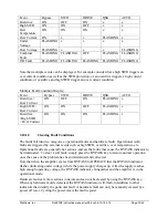
Error Status Display
The following table indicates the fault codes displayed for each event:
Summary of Contents for DX2400L1
Page 11: ...Dishtronix Inc Dx2400l1 instruction manual rev00 doc 06 10 18 5 14 Page 11 44 2 INSTALLATION...
Page 19: ...Dishtronix Inc Dx2400l1 instruction manual rev00 doc 06 10 18 5 14 Page 19 44 3 OPERATION...
Page 41: ...Dishtronix Inc Dx2400l1 instruction manual rev00 doc 06 10 18 5 14 Page 41 44 5 SERVICE...
Page 44: ...Dishtronix Inc Dx2400l1 instruction manual rev00 doc 06 10 18 5 14 Page 44 44 NOTES...


