


Dishtronix, Inc.
Dx2400l1 instruction manual rev00.doc 06-10-18 5.14
Page 33/44
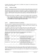
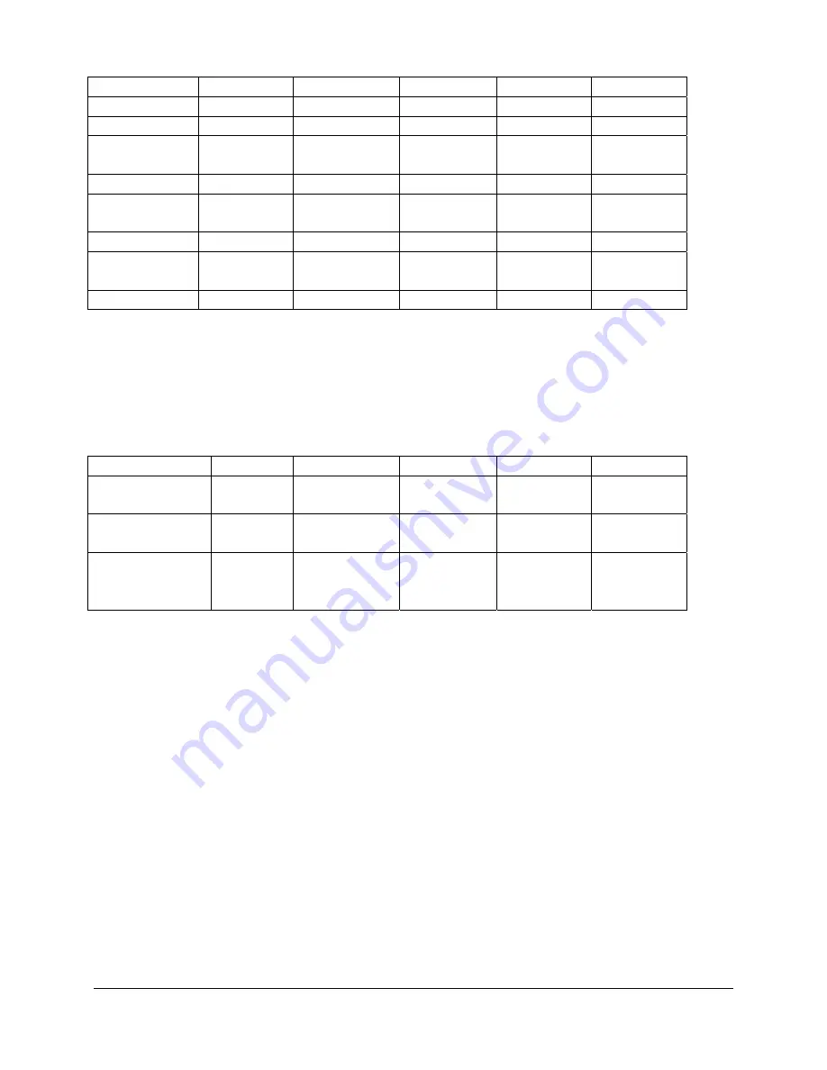
Event Bypass
SWR DRIVE
QSK
AUTO
Overdrive ON
OFF
ON
x
x
High SWR
ON
ON
OFF
x
x
Over
Temperature
ON ON ON x x
Over Current
ON
x
x
FLASHING x
Under
Voltage
FLASHING x
x
x
x
Over Voltage
FLASHING x
x
x
FLASHING
Combiner
Fault
FLASHING FLASHING OFF
FLASHING FLASHING
T/R Fault
FLASHING FLASHING
FLASHING FLASHING FLASHING
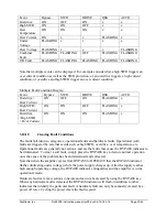
Note that multiple events can be displayed. For example consider that a high SWR triggers an
over current condition as well as the SWR protection, or an overdrive triggers a high current
condition, or overdrive and high SWR trigger an over current condition:
Multiple Fault Condition Display:
Event Bypass
SWR
DRIVE
QSK
AUTO
Ove
Over Current
ON OFF
ON FLASHING
x
High SWR+
Over Current
ON ON
OFF FLASHING
x
Overdrive
+High SWR
+ Over Current
ON ON
ON FLASHING
x
3.10.10
Clearing Fault Conditions
The faults fall into two categories, operational faults and hardware faults. Operational (soft)
faults are triggered by external events such as high SWR, overdrive, over temperature, etc.
Operational faults are generally not serious, and are the faults that cause the BYPASS indicator to
be illuminated. To clear a soft fault, simply press the BYPASS key to restore normal operation
once the cause of the problem has been determined and corrected.
Note that when the amplifier cycles from BYPASS to OPERATE that the BYPASS indicator
flashes (indicating under voltage) while the power supply charges up. After the supply reaches
high enough operating voltage, the BYPASS indicator extinguishes and the amplifier is in the
operational mode.
Hardware faults are more serious in nature and can not be cleared by using the BYPASS key.
When any hardware fault is detected, the BYPASS indicator will flash, in addition to other
indicators that identify the particular fault. A hardware fault can only be manually cleared by a
power off reset. Cycling the power clears the fault register.
Summary of Contents for DX2400L1
Page 11: ...Dishtronix Inc Dx2400l1 instruction manual rev00 doc 06 10 18 5 14 Page 11 44 2 INSTALLATION...
Page 19: ...Dishtronix Inc Dx2400l1 instruction manual rev00 doc 06 10 18 5 14 Page 19 44 3 OPERATION...
Page 41: ...Dishtronix Inc Dx2400l1 instruction manual rev00 doc 06 10 18 5 14 Page 41 44 5 SERVICE...
Page 44: ...Dishtronix Inc Dx2400l1 instruction manual rev00 doc 06 10 18 5 14 Page 44 44 NOTES...


