User manual in Original
Doc. ref: 500A_GTS-E65_am_en_210608
DISPERATOR AB
Tel: 08-724 0160
E-mail: info@disperator.se
Mälarvägen 9, 141 71 Segeltorp
Web page: www.disperator.se
24 / 48
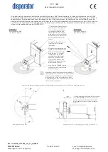
6.4.7. Direction of Rotation for the Disposer and the Pump
a) The disposer operates correctly irrespective of the motor’s rotational
direction. It is therefore irrelevant in which sequence the electrical phases
are connected to the disposer motor.
IMPORTANT
b) However, the correct function of the GTS-processor pump is dependent on
the pump rotating in the correct direction, which is shown by an arrow on
the serial number plate. In other words seen from the pump motor drive
side, its axis with the rotor shall rotate counterclockwise. Check the pump
rotation by only for a short moment start the GTS-processor. If the shaft of
the rotor does not rotate counterclockwise, change the sequence of the connection of the
pump motor’s three phases.
Checking that the pump has the correct direction of rotation can also be done by starting
the GTS processor for a short moment, while holding the handset for the machine’s outlet. If
there is an overpressure (ie ”pump blows out”) at the outlet, the pump will rotate properly.
If there is a negative pressure (ie ”the pump sucks”), the electrical phases must be switched
over.
6.4.8. Protective Cover Connected to Safety Interlock Switch
a) Check the function of the safety interlock switch. The machine and its motor idling speed
must stop before the protective cover above disposer inlet has been
released and removed.
b) If necessary, fine-tune the positioning of this switch and make sure it is
properly fixed.
c) Ensure that the key mounted on the protective cover can easily move in
and out of this switch.
d) Also make sure that the important mechanical seal around this key is in place and in good
condition.
6.4.9. Sensor for Monitoring Pump Temperature
The sensor for monitoring the pump operating temperature, is placed in the pump stator, and are
ready connected from the factory. The pump’s operating temperature as given from this sensor
is shown on the display located in the enclosure placed on the inside of the cabinet’s right-hand
door. For more information, see section 6.5. below, and if necessary, Chapter 13 of the
pump’s
operating and maintenance instructions in original as enclosed.
Summary of Contents for 500A-GTS-E65 EXCELLENT SERIES
Page 2: ......

