background image

Subnetwork Installation Guidelines

Network Guide

81

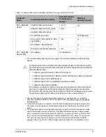
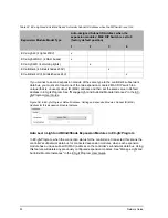
room devices and ECx-4XX Series I/O Extension Module EOL terminations are factory set to 
OFF (except for the EC-Multi-Sensor).

EOL Terminations for the ECB/ECL-VAV Series, ECB/ECL-103 to -400 Series, 
and ECB/ECL-PTU Series Controllers

When one or more room devices are connected to the Subnet Port of an ECB/ECL-VAV 
series, ECB/ECL-103 to -400 Series, or ECB/ECL-PTU Series controllers, only the EOL termi-
nations of the last room device is set to ON. All other room devices on the subnetwork data 
bus must have their EOL terminations set to OFF. The controller must be the first device on 
the Cat 5e Cable Subnetwork data bus as its internal EOL termination is permanently enabled. 
The ECx-Display does not have any EOL terminations to be set and as such should not be 
installed as the last device on the subnetwork bus. See 

Figure 47

.

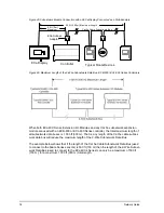
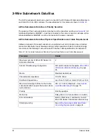
For the Cat 5e Cable subnetwork data bus, only a daisy-chain 
topology is acceptable and T-connections are not allowed. For the 
EC-Multi-Sensor and ECx-Display, an optional ECx-Subnet 
Adapter (Y-splitter) is available to facilitate the daisy-chain connec-
tion of these devices. The male-end of the ECx-Subnet Adapter 
must be connected directly to the device and its length cannot be 
extended.

Figure 50: An ECx-Subnet Adapter (Y-Splitter)

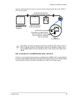
The ECx-Subnet Adapter is also used with a controller to connect 
to an ECX-Display and to one or more room devices. See 

Figure 

47

. In this scenario, the male-end of the ECx-Subnet Adapter must 

be connected directly to the controller’s 

Subnet Port 

and its length 

cannot be extended.

Summary of Contents for ECB-VAV

Page 1: ...User Guide Network Guide...

Page 2: ...afe environments Distech Controls reserves the right to change delete or add to the information in this manual at any time without notice Distech Controls the Distech Controls logo and Innovative Solu...

Page 3: ...uilt in EOL Terminations 22 Only a Daisy Chained Data Bus Topology is Acceptable 22 Data Bus Shield Grounding Requirements 24 ECB 24V Powered Controller Data Bus Shield Grounding Requirements 24 ECB P...

Page 4: ...work Data Bus Cable Requirements 79 Cat 5e Cable Subnetwork Bus Topology and End of Line Terminations 80 Setting the Subnet ID Addressing for Room Devices 84 Setting the Allure EC Smart Air and EC Sma...

Page 5: ...ies I O Extension Module Specific Troubleshooting 121 CHAPTER 9 Allure EC Smart Vue Sensor Troubleshooting 123 CHAPTER 10 ECx Light Blind Series Troubleshooting 127 APPENDIX A Typical BACnet EIA 485 D...

Page 6: ...Table of Contents 4 Network Guide...

Page 7: ...Introduction Network Guide 5 CHAPTER 1 Introduction This section provides an overview of the user guide Topics Introduction About This User Guide Acronyms and Abbreviations...

Page 8: ...SI CEA 709 1 B specifies a number of Local Area Network LAN transport types Distech Controls controllers use a twisted pair free topology communica tions data bus operating at 78 kbit s as a local net...

Page 9: ...ices connected to the LAN to use network management tool software to program a device to share points on the network or the procedure to install a given device For this information refer to the device...

Page 10: ...entation The follow documentation is referenced in this document Controller Hardware Installation Guides These documents are available on Distech Controls SmartSource website EC gfxProgram User Guide...

Page 11: ...e text Wherever the note paper icon appears it means the associated text is giving a time saving tip or a reference to associated information of interest This is an example of Caution or Warning text...

Page 12: ...col B AAC BACnet Advanced Application Controller B ASC BACnet Application Specific Controller B BC BACnet Building Controller BBMD BACnet IP Broadcast Management Device DALI Digital Addressable Lighti...

Page 13: ...ission Essentials Maximum Number of BACnet MS TP Devices on a Data Bus Segment and Baud Rate Data Bus Physical Specifications and Cable Requirements Data Bus Topology and EOL Terminations Data Bus Shi...

Page 14: ...hat are daisy chained together are allowed with BACnet MS TP see Figure 5 A spur is only permit ted when it is connected to the data bus through a repeater see Using Repeaters to Extend the Data Bus o...

Page 15: ...the BACnet MS TP data bus to the Reference terminal See Data Bus Shield Grounding Requirements on page 24 for more information Table 2 Common Identification Labels for BACnet MS TP Data Bus Polarity...

Page 16: ...between devices The recommended baud rate is 38 400 See Baud Rate on page 16 Distech Controls recommends that you connect no more than 50 of our or load devices on a single BACnet MS TP Data Bus Segme...

Page 17: ...t MS TP Data Bus The solution for the above example is to create two data bus segments connected together by a repeater and then split up the devices between the data bus segments ensuring again that...

Page 18: ...or example set the baud rate of the EC BOS if equipped and one other controller to 38 400 baud If the EC BOS becomes unavailable and there is a power cycle the controller will set the baud rate for th...

Page 19: ...MS TP Communication Data Bus Fundamentals Network Guide 17 Only a Daisy Chained Data Bus Topology is Acceptable Use a daisy chained BACnet MS TP data bus topology only No other data bus topology is a...

Page 20: ...eld Shield grounding The shield on each segment is connected to the electrical system ground at one point only see Data Bus Shield Grounding Require ments on page 24 Characteristic impedance 100 130 O...

Page 21: ...entals Network Guide 19 Distech Controls BACnet cable offers the best performance over the full range of baud rates cable lengths and number of connected devices This is primarily due to lower conduct...

Page 22: ...e transmitter is in the idle state it is effectively offline or dis connected from the data bus EOL terminations serve to bias pull down and pull up each data line wire when the lines are not being dr...

Page 23: ...Cnet MS TP thermostat at one end of the BACnet MS TP data bus and an EC BOS at the other end you must set the built in EOL termination in the EC BOS so that proper biasing is provided to the BACnet MS...

Page 24: ...terminations Only a Daisy Chained Data Bus Topology is Acceptable Use a daisy chained BACnet MS TP data bus topology only No other data bus topology is allowed Figure 5 Typical BACnet MS TP LAN Topol...

Page 25: ...BACnet MS TP Communication Data Bus Fundamentals Network Guide 23 Figure 6 Unsupported BACnet MS TP LAN Topologies...

Page 26: ...BACnet MS TP data bus simply connect the data bus shield to the COM ter minal see Figure 15 ECB 24V Powered Controller Data Bus Shield Grounding Requirements The shield on each data bus segment must...

Page 27: ...olate with electrical tape Typical BACnet24VAC Powered Controller Typical BACnet24VAC Powered Controller Data Bus Shielded Twisted Pair Cable NET NET NET NET NET NET Bus Master Building Controller Typ...

Page 28: ...Line Powered Controller Data Bus Shields Twist Together and Connect to COM Terminal NET NET COM Typical BACnet Line Powered Controller Data Bus Shield Connect to COM Terminal NET NET COM Typical BACne...

Page 29: ...st together and Isolate with electrical tape Typical BACnet24VAC Powered Controller Data Bus Shielded Twisted Pair Cable NET NET NET NET Typical BACnet24VAC Powered Controller NET NET Data Bus Shield...

Page 30: ...peater is a bi directional device that regenerates and strengthens the electrical signals that pass through it It creates two electrically isolated BACnet MS TP data bus segments that transparently en...

Page 31: ...n be used to create a spur as shown below Figure 17 Adding a Spur by Using a Repeater A repeater is counted as a device on each data bus to which it is connected When third party devices are connected...

Page 32: ...d of this data bus See When to Use EOL Terminations on page 20 for more information The shield of one data bus must be grounded at one point as specified in see Data Bus Shield Grounding Require ments...

Page 33: ...located elsewhere in the internetwork Unlike a MAC Address a Device Instance cannot be reused elsewhere in the BACnet internetwork it must be unique for the entire network The Network Number is any n...

Page 34: ...a Bus It is the timeout for each unassigned MAC Address that slows down the data bus The way MAC Addresses are assigned is not a physical requirement Devices can be daisy chained on the data bus in an...

Page 35: ...us Master Building Controller should have the Max Info Frames param eter set to 20 About Tuning the Max Master Parameter To prevent the passing of the token to unused MAC Addresses situated after the...

Page 36: ...r the Max Master by finding the highest Master device MAC Address on the connected BACnet MS TP data bus plus 1 Sets the Max Master for all master devices including the Data Bus Master EC BOS Sets the...

Page 37: ...2 The Configure Ms Tp devices dialog box is displayed The network must be live the Sta tus shown in Configure Ms Tp devices window must be ok Figure 20 Setting the Max Master on the Data Bus Master EC...

Page 38: ...fficient for a BACnet network that has only one Building Control ler For larger BACnet networks that have more than one Building Controller to form a BACnet intranetwork set the MAC Addresses Device I...

Page 39: ...000 to 4 190 000 10 000 20 000 BACnet MS TP Network Number Building Controller BACnet IP Device Instance Num ber 1000 0 1 2 3 4 for each LAN 10 to 4190 10 11 12 BACnet MS TP Device Instance Number EC...

Page 40: ...controller on the left and for a Distech Controls ECB PTU 208 controller on the right Figure 23 Typical Device MAC Address DIP Switch Set to 82 The address is the sum of the numbers set to ON For exam...

Page 41: ...set with an Allure EC Smart Vue sensor the change is made immediately without any need to power cycle the controller Setting the Controller s MAC Address Through the color LCD Screen of a 50 Series C...

Page 42: ...he BACnet IP Broadcast Man agement Device BBMD service to be configured and operational The BBMD service identifies BACnet messages on the BACnet MS TP network that are intended for a device located o...

Page 43: ...devices a voltage will develop over the length of wire For example a 1000 ft of 18 AWG cop per wire has a resistance of 6 4 Ohms If this wire is supplying 1 Ampere of current to con nected devices as...

Page 44: ...n calculating a controller s power consumption to size the 24VAC transformer you must also add the external loads the controller is going to supply including the power consumption of any connected sub...

Page 45: ...going to supply including the power consumption of any connected subnet module for example Allure Series Communicating Sensors If only one 24VAC transformer is available determine the maximum number...

Page 46: ...artVue 2DO 1 6VA each AWG18 VAV SmartVue 2DO 1 6VA each AWG16 VAV SmartVue SmartVue CO2 2DO 1 6VA each AWG18 VAV SmartVue SmartVue CO2 2DO 1 6VA each AWG16 A B C D E F A B C D E F 30 60 90 120 150 180...

Page 47: ...ls recommended power cable 24VAC Power Supply Connection Use an external fuse on the 24VAC side secondary side of the transformer as shown in Fig ure 28 to protect all controllers against power line s...

Page 48: ...the same electrical potential Figure 28 Power Wiring diagram As specified by electrical safety codes worldwide the building s protective ground network must not be used to conduct electrical current...

Page 49: ...See Transformer Selection and Determining the Maximum Power Run Length on page 43 for how to choose an appropriate transformer One terminal on the second ary side of each of these transformers must b...

Page 50: ...ax Fast Acting 24 VAC Transformer MANDATORY 24V COM Terminal Must be Connected to Electrical System Ground At the Transformer s Secondary Only Subnetwork Bus Cable Shield Must be Connected to Electric...

Page 51: ...BACnet MS TP Communication Data Bus Fundamentals Network Guide 49 Typical Device BACnet MS TP LAN and Power Wir ing Diagram An overview of the BACnet MS TP LAN and power wiring is shown below...

Page 52: ...50 Network Guide...

Page 53: ...us Funda mentals This chapter describes the LONWORKS Communications Bus operating principles Topics Network Architecture TP FT 10 Network Topologies Extending the Network Grounding a Network Power Sup...

Page 54: ...network connections for LON WORKS controllers Single Segment EC Net Network A single segment EC Net Network shown with EC Net Supervisor and EC Net Pro Figure 30 Single Segment EC Net Network Inter B...

Page 55: ...LonWorks Communication Bus Fundamentals Network Guide 53 Figure 31 Typical Inter Building Connection Using IP FOX...

Page 56: ...gy A bus topology is a physical routing of the communication channel that includes a distinct beginning and end It is also known as a daisy chain topology Figure 32 Figure 3 3 Bus Topology TP FT 10 Bu...

Page 57: ...ths exist i e a loop topology then the longest path should be used for calculations The maximum total wire length is the total length of wire within a segment See Network Cables on page 55 for detaile...

Page 58: ...es All wiring must comply with applicable national state and local wiring electrical codes ordinances and regulations Table 11 TP FT 10 Channel Attributes Parameter Details Nickname Free Topology Raw...

Page 59: ...s 10 feet NEC Rating UL listed art 800 plenum CSA Flame rated Untwisted wires or cables containing flat or parallel untwisted conductors must not be used on an LONWORKS twisted pair channel The use of...

Page 60: ...he maximum length is 500 meters 1640 feet node to node and 500 meters 1640 feet total wire length For more information about extending the network to a sensor see Connecting to the LAN through an Allu...

Page 61: ...ble the over all system capability A maximum of 128 devices per channel can be installed on a TP FT 10 However after 64 devices you must add a repeater in order to add more devices up to the 128 devic...

Page 62: ...st once per segment and preferably at each node Grounding the shield at every node using the shield grounding circuit shown in Figure 35 will assist in suppressing 50 60Hz standing waves Building Entr...

Page 63: ...r Run Length It is recommended to wire only one controller per 24VAC transformer When calculating a controller s power consumption to size the 24VAC transformer you must also add the external loads th...

Page 64: ...0 500 600 700 800 900 1000 Max VAV in Daisy Chain Total Wire Length in Feet Daisy Chain Performance VAV SmartVue AWG18 VAV SmartVue AWG16 VAV SmartVue 2DO 1 6VA each AWG18 VAV SmartVue 2DO 1 6VA each...

Page 65: ...e Laboratory testing conditions for the above graph are as follows Distance between each VAV is evenly spaced along the entire wire length Transformer specification 100VA 120 24VAC Tested at room temp...

Page 66: ...s the 24V COM terminal of each controller and each peripheral should be connected to the same terminal on the secondary side of the transformer Figure 38 Power wiring 24VAC Maintain Consistent Polarit...

Page 67: ...M 24 VDC 24 VAC AC Power Source 24 120 208 240 277 347 480 VAC 1 2 Wire plus Ground 24V COM 24V AC DC BACnet Device Power Supply Fuse 4A Max Fast Acting C RC BACnet Thermostat 24 VAC COM to Ground At...

Page 68: ...tion and Determining the Maximum Power Run Length on page 61 for how to choose an appropriate transformer One terminal on the second ary side of each of these transformers must be connected to the bui...

Page 69: ...Max Fast Acting 24 VAC Transformer ECx 4XX 24V AC DC 24V COM Fuse 4 A Max Fast Acting 24 VAC Transformer ECL 600 24V AC DC 24V COM MANDATORY 24V COM Terminal Must be Connected to Electrical System Gr...

Page 70: ...68 Network Guide...

Page 71: ...bnetwork supports a range of expansion extension modules Topics About the Subnetwork Data Bus Cat 5e Cable Subnetwork Data Bus Setting the Allure EC Smart Air and EC Smart Comfort Communicating Sensor...

Page 72: ...ort is collectively referred to as room devices In addition the ECB 600 and ECL 600 Series controllers can be connected to one or two ECx 4XX I O Extension Modules using the same subnetwork data bus h...

Page 73: ...Subnetwork Module Compatibility and Maximum Supported Quantity Chart Controller Model Subnetwork Data Bus Device Permitted Subnet ID Addressing Range1 Maximum Quantity Allowed ECL VAV ECB VAV Allure...

Page 74: ...x Light 4DALI 1 to 4 25 ECx Blind 4 ECx Blind 4LV 25 ECx 4XX I O Extension Modules Not Supported ECL ECB 203 Models Only ECx Display Not Applicable 1 ECL ECB 300 Series ECL ECB 400 Series Allure EC Sm...

Page 75: ...600 Series Allure EC Smart Vue series 1 to 12 123 Allure EC Smart Comfort series 1 to 6 Allure EC Smart Air series EC Multi Sensor series Not Supported ECx Light 4 ECx Light 4D ECx Light 4DALI 1 to 4...

Page 76: ...CB ECL VAV Series ECB PTU ECL PTU Series ECB ECL 103 ECB ECL 203 Series ECB ECL 300 Series ECB ECL 400 Series For use with an ECB 600 ECL 600 Series Controller Only 2 Wire Subnetwork Bus Cat 5e Cable...

Page 77: ...aximum length of all subnetwork data buses is 1 000 ft 300 m of which the length of the Cat 5e subnetwork data bus can be no more than 600 ft 180 m See Figure 47 See below Figure 44 Maximum Length of...

Page 78: ...is 1 000 ft 300 m That is any length of the Cat 5e cable subnet work data bus will reduce the maximum length of the 2 Wire Subnetwork Data Bus The example below shows that if the length of the Cat 5e...

Page 79: ...th 1 000 ft 300m Example 500 ft 150 m Cat 5e Cable Subnetwork Bus Length 600 ft 160 m Example 500 ft 150 m Subnetwork Bus Total Length Up to 1 000 ft 300m Maximum 2 Wire Subnetwork Bus Cat 5e Cable Su...

Page 80: ...with 12 Allure Series sensors in total then 10 Allure Series sensor models must be without a CO2 sensor and the remaining two 2 Allure Series sensor models can be equipped with a CO2 sensor To ensure...

Page 81: ...esult Table 17 Cat 5e Cable Subnetwork Data Bus Physical Specifications and Cable Requirements Parameter Details Maximum number of room devices See Subnetwork Module Compatibility and Supported Quan t...

Page 82: ...Not applicable Table 17 Cat 5e Cable Subnetwork Data Bus Physical Specifications and Cable Requirements Parameter Details Table 18 Distech Controls Recommended Cable Types to use for the Cat 5e Cable...

Page 83: ...mination is permanently enabled The ECx Display does not have any EOL terminations to be set and as such should not be installed as the last device on the subnetwork bus See Figure 47 For the Cat 5e C...

Page 84: ...L set to ON at the last sensor at the end of the Bus ON EOL OFF Controller Series ECL VAVS ECL VAV ECL PTU ECL 103 ECL 203 ECL 300 ECL 400 Back of Allure EC Smart Vue ECB VAVS ECB VAV ECB PTU ECB 103...

Page 85: ...re Series sensors must have their EOL terminations set to OFF This is shown below Depending on the type of expansion module the subnetwork data bus EOL may be set by configuring jumpers or DIP switche...

Page 86: ...5e Cable Subnetwork Bus Controller Series ECB 600 ECL 600 For ECB 600 ECL 600 set the Subnetwork EOL to ON EOL OFF EOL ON Inside ECB ECL 600 EOL set to ON at the last sensor at the end of the Bus ON...

Page 87: ...D ECx Light 4DALI ECx Blind 4 ECx Blind 4LV DIP switch located next to Subnet Port connectors Setting the ECx Light and ECx Blind Series Subnet on page 75 Table 19 Subnetwork Module Compatibility and...

Page 88: ...This address should corre spond to the block number of the associated Subnet Extension block in EC gfxProgram The address is set through a DIP switch located inside the sensor near the RJ 45 connector...

Page 89: ...et the EOL termination to ON Allure EC Smart Comfort EC Smart Air Front Cover Interior View Setthe Subnet ID Address EOL Termination RJ 45 Subnetwork Pass Through Connectors Table 20 Allure EC Smart A...

Page 90: ...ion is ON Once an EC Multi Sensor is installed the following tip can be used during system commissioning to verify if the EC Multi Sensor is set to the correct subnet ID address for the zone in which...

Page 91: ...dress for Light and Blind Expansion Modules Often only one type of expansion module is connected to the controller for example one ECx Light 4 and one ECx Blind 4 model By leaving the Subnet ID addres...

Page 92: ...he connection status for the controller is Connected this scans the controller s subnetwork data bus for connected expansion modules when each expansion module has a unique subnet ID MAC address on th...

Page 93: ...Options Learn is only available after 2 minutes of the controller having been powered up This information is no longer available after 30 minutes Reboot the controller if Learn is unable to find the c...

Page 94: ...h Controls strongly recommends the following 2 wire subnetwork data bus cable specifications be respected Table 23 Cat 5e Cable Subnetwork Data Bus Physical Specifications and Cable Requirements Param...

Page 95: ...ed to an ECB 600 ECL 600 controller s Subnet and Subnet connectors and with one or more Allure Series sensor s are connected to the controller s Subnet Port only the EOL terminations of the last ECx 4...

Page 96: ...bus cable must be connected to the electrical system ground at one point only preferably at the ECB 600 ECL 600 as shown below Figure 62 ECB 600 ECL 600 2 Wire Subnetwork Data Bus Shielding For use wi...

Page 97: ...sing Each ECx 4XX I O Extension Module on a 2 Wire subnetwork data bus needs to be set to a unique address The address is set through the DIP switch located on the ECx 4XX I O Exten sion Module s face...

Page 98: ...and each associated ECx 4XX I O Extension Module must have their own dedicated power supply To size the power supply transformer see Transformer Selection and Determining the Maximum Power Run Length...

Page 99: ...PTER 5 Controller Installation and Maintenance Tasks with an Allure EC Smart Vue Sensor This chapter describes how to use an Allure EC Smart Vue sensor to perform installation and maintenance tasks in...

Page 100: ...t Vue sensor s Subnet ID can be set in the procedure below ECB and ECL Series controllers can be commissioned with an Allure EC Smart Vue sensor The default Subnet ID for an Allure EC Smart Vue sensor...

Page 101: ...e next for commissioning purposes When the controller has been programmed each connected Allure EC Smart Vue s Sensor must be assigned a unique Subnet ID Commissioning Controllers To commission a cont...

Page 102: ...the display 5 Press the down button once to enter the GEN CFG submenu The MAC ADDRESS menu is shown with the current controller s BACnet MAC Address 6 Use the up and down buttons to set the controlle...

Page 103: ...ovide failover service In this scenario should the first controller that is to set the baud rate fail or should it take longer than usual to boot after a power failure this second failover controller...

Page 104: ...nu button for 5 seconds to exit the configuration menu Connecting to the LAN through an Allure EC Smart Vue Sen sor The Cat 5e Cable subnetwork data bus extends the LAN to the Allure EC Smart Vue sens...

Page 105: ...nection No EOL Resistors are Necessary Typical Adaptor Network Interface Cat 5e Cable Subnetwork Bus Typical ECB ECL Series Controller Table 26 LAN through an Allure EC Smart Vue Sensor Feature Compat...

Page 106: ...l ogy refer to Network Cables on page 55 The length of the Allure EC Smart Vue sensor subnetwork data bus must also comply with the restrictions shown in Subnetwork Data Bus Length on page 75 Enabling...

Page 107: ...4 Dip Switch and Jumper Identification and Configuration Enable Disable Enable Disable Net to Subnet Port Settings Factory default positions FUSE Cover Removed Jumpers for DO1 DO2 Jumpers for DO3 DO4...

Page 108: ...re EC Smart Vue sensor Then wire a standard 3 5 mm three con ductor stereo jack or two conductor mono jack as shown below Figure 69 1 8 3 5 mm Stereo or Mono Jack Connection for a LONWORKS Network Int...

Page 109: ...Adapter The following BACnet MS TP adapter is available from Distech Controls BACnet IP to MS TP Adapter part number NC BASRTPBXX The BACnet MS TP adaptor must have an electrically isolated RS 485 por...

Page 110: ...108 Network Guide...

Page 111: ...ck the fuse integrity Reconnect the power Power supply polarity Verify that consistent polarity is maintained between all controllers and the trans former Ensure that the COM terminal of each controll...

Page 112: ...ler with the same Device ID on the BAC net intranetwork Each controller on a BACnet intranetwork the entire BACnet BAS network must have a unique Device ID Use an Allure series communicating sensor to...

Page 113: ...dule s hardware installation manual and according to the peripheral device s manufacturer recommendations Open circuit or short circuit Using a voltmeter check the voltage on the input terminal For ex...

Page 114: ...lution Table 28 LED Fault Condition Interpretation for ECB Devices ECB Device LED Interpretation Description Solution RX LED not blinking Data is not being received from the BACnet MS TP data bus If t...

Page 115: ...150ms On 300ms Off 150ms On 300ms Off 800 ms On Poor quality power The device has browned out for 24V controllers The voltage at the 24VAC DC and 24VCOM terminals was not at an acceptable level during...

Page 116: ...e address holes in the device s MAC Address range Assign MAC Address to device starting at 3 up to 127 Do not skip addresses Set the maxi mum MAC Address in the ECY Series Controller to the final MAC...

Page 117: ...nsure that it is within acceptable limits for 24V controllers 3 Check for tripped fuse or circuit breaker Overloaded power transformer for 24V controllers 1 Check if the device is showing the Poor Pow...

Page 118: ...e statistic to check errors Use a LON protocol analyzer to check network traffic Hardware input is not reading the correct value Input wiring problem Check that the wiring is correct according to the...

Page 119: ...for example is it enabled Refer to the EC gfxProgram User Guide for more information Table 32 Troubleshooting ECL Device Symptoms Symptom Possible Cause Solution Table 33 LED Fault Condition Interpret...

Page 120: ...0ms Off 150ms On 300ms Off 150ms On 300ms Off 150ms On The controller is in bypass mode Set the controller Online Short Short Long blink 150ms On 300ms Off 150ms On 300ms Off 800 ms On Poor quality po...

Page 121: ...LonWorks Troubleshooting Network Guide 119...

Page 122: ...120 Network Guide...

Page 123: ...ak and pull a new cable Overloaded power transformer Verify that the transformer used is powerful enough to supply all controllers See ECx 4XX I O Extension Module Power Supply Requirements on page 47...

Page 124: ...122 Network Guide...

Page 125: ...d Symptom Possible Cause Solution Allure EC Smart Vue sen sor screen is blank back light is off Is the Allure EC Smart Vue sensor connected to the controller Verify that the Allure EC Smart Vue sensor...

Page 126: ...ensor is connected to a controller its firmware is loaded from the controller In this case the controller has an earlier version of Allure EC Smart Vue sensor firmware that does not support the motion...

Page 127: ...l icon Allure EC Smart Vue sen sor is not properly config ured in the controller With EC gfxProgram check the configuration of the sensor for exam ple is the ComSensor block enabled Refer to the EC gf...

Page 128: ...126 Network Guide...

Page 129: ...that the RJ 45 crimp connectors were installed on the cable cor rectly See Cat 5e Cable Subnetwork Data Bus Cable Requirements on page 79 Expansion module is not communicating with control ler Is the...

Page 130: ...mple is it enabled Refer to the EC gfxProgram User Guide for more infor mation Over voltage or over cur rent at an input An over voltage or over current at one input can affect the reading of other in...

Page 131: ...t to the Net connection Figure 72 Example of a Typical EIA 485 Data Bus Transmission The permitted voltage levels of an EIA 485 transmitter and receiver are shown below Figure 73 Typical EIA 485 Data...

Page 132: ...The receiver nulls out common mode induced noise picked up on the data bus wire by subtracting the negative input from the positive input This greatly reduces the impact that induced noise has on the...

Page 133: ...1 110 111 0000 0 1 2 3 4 5 6 7 0001 8 9 10 11 12 13 14 15 0010 16 17 18 19 20 21 22 23 0011 24 25 26 27 28 29 30 31 0100 32 33 34 35 36 37 38 39 0101 40 41 42 43 44 45 46 47 0110 48 49 50 51 52 53 54...

Page 134: ...132 Network Guide Figure 75 Example of How to Set a DIP Switch to 82 ON B A For example 82 A 1010 B 010...

Page 135: ...equivalents for wire gauge AWG Diameter Area Approximate stranded metric equivalents Inch mm kcmil mm2 10 0 1019 2 588 10 4 5 26 12 0 0808 2 053 6 53 3 31 14 0 0641 1 628 4 11 2 08 16 0 0508 1 291 2 5...

Page 136: ...134 Network Guide...

Page 137: ...Network Guide...

Page 138: ...Network Guide_UG_24_EN...

Reviews: