background image

Chapter 1: Introduction 


Operation Manual: VIP 4400 Vessel Washer 

1-6


In the event of a hazardous material spill on 
the external surface of the instrument, the 

unit can be cleaned with a disposable cloth or 

paper wipe, then rinsed and dried with water.  
The same approached can be used for internal 
spill but the power must be disconnected first! 


Prior to performing any cleaning or 
decontamination method, the user should 
verify the method with Distek.


Improper remote PC control of the VIP 4400      
system may lead to unexpected pump and/or 
heater operation. 


The VIP 4400 is supplied with proper 
components and settings for the specified 
operating voltage (see label for information).  
Do not attempt to convert unit to another 
mains supply without contacting Distek's 
factory first! 


External cables (excluding power cable) are 
limited to less than 3 meters length in order to 

maintain electromagnetic compliance. 


Some forms of electromagnetic interference may 
cause unexpected operation.  If this occurs, the 

unit will return to normal operation once the 
interference is removed. 


Summary of Contents for VIP 4400

Page 1: ...Operation Manual VIP 4400 Vessel Washer Operation Manual VIP 4400 Vessel Washer ...

Page 2: ...ion Manual VIP 4400 Vessel Washer VIP 4400 Vessel Washer Operation Manual Document 3844 0002 Distek Inc 121 North Center Dr North Brunswick NJ 08902 Phone 732 422 7585 Fax 732 422 7310 http www distekinc com ...

Page 3: ...o part of this document may be photocopied reproduced or translated without the prior written consent of DISTEK Incorporated DISTEK INC 121 North Center Drive North Brunswick NJ 08902 4905 Tel 732 422 7585 Fax 732 422 7310 Website http www distekinc com Document Revision History Rev Date Notes A 5 20 05 Initial Release ...

Page 4: ...tal Considerations 1 3 Ambient Laboratory Temperatures 1 3 Ambient Laboratory Humidity 1 4 Air Quality Considerations 1 4 Operation Warnings and Notes 1 5 General Instrument Overview 1 7 2 Installation 2 1 Unpacking 2 2 System Setup 2 2 Installation Checkout 2 2 3 Operation 3 1 Main Control Keypad 3 2 Remote Nozzle Keypad 3 3 Filling the Rinse Tank 3 4 Using the Vessel Washer 3 5 Using the Manual ...

Page 5: ... 3 11 Cleaning or Replacing the Filter and Filter Bottle 3 12 Using an Antifoaming Agent 3 13 4 Maintenance 4 1 General Information 4 2 Cleaning the Tanks 4 2 Opening the Top Cover 4 3 Tubing Replacement 4 3 Cleaning the Water Inlet Valve Filter 4 4 Temperature Calibration 4 5 5 Troubleshooting 5 1 Troubleshooting 5 2 Error Codes 5 3 Service 5 4 Appendix A Spare Parts and Accessories A 1 Appendix ...

Page 6: ...l VIP 4400 Vessel Washer i About this Manual About This Manual includes information about what is contained in this manual and the conventions used Purpose ii Audience ii Contents ii Prerequisites iii Documentation iii Conventions iii ...

Page 7: ...eral overview of the instrument Chapter 2 Installation Describes how to unpack and properly install and qualify the unit Chapter 3 Operation Describes the operation of the unit Chapter 4 Maintenance Explains the steps necessary to maintain the unit Chapter 5 Troubleshooting Provides a troubleshooting chart and description of error messages to assist the user if a problem should arise Appendix A Sp...

Page 8: ...following table contains Warnings Cautions and Notes that are used throughout the document for your protection Please read this section before using the instrument WARNING statements are used in this manual to prevent injury to personnel Electrical hazard warning Use caution as high voltage may exist CAUTION statements are used to prevent damage to equipment NOTES contain helpful information REQUI...

Page 9: ...minimize the time in between dissolution tests This chapter will provide an overview of the unit and system specifications Overview 1 2 Specification 1 2 Physical Site Considerations 1 3 Environmental Considerations 1 3 Ambient Laboratory Temperatures 1 3 Ambient Laboratory Humidity 1 4 Air Quality Considerations 1 4 Operation Warnings and Notes 1 5 General Instrument Overview 1 7 ...

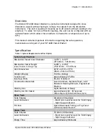
Page 10: ...ications Dissolution Vessel Inner Diameter 3 970 0 125 97 66mm 104 01mm Dissolution Vessel Height Vessel Bottom to Flange Top 6 485 0 250 158 37mm 171 07mm Unit Dimensions 26 W x 26 D x 39 H 66cm x 66cm x 99cm Weight Empty 150 lbs 68 kg Sound Level Approximately 65 dB A Interface Ports RS 232 USB 2 0 Construction Materials Cast Aluminum Stainless Steel Acid Resistant Heating Element Engineered Pla...

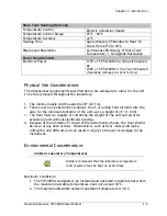
Page 11: ...eeded is 28 0 71m 2 There must be no obstruction cabinet shelf or outlet that intrudes into the aisle for the minimum footprint of the unit up to a height of 45 1 14m 3 The floor must be capable of sustaining the weight of the unit and all of its accessory parts without significant bending 4 Because of the limitation in travel of the instruments wheels the floor should be clear of any obstructions...

Page 12: ...n chloride vapor from dissolution media can cause serious effects when condensed on electrical components and contacts The lab s environmental controls should maintain the humidity level below the dew point to minimize the risk of condensation Minimum It is important that the humidity level be kept at or above 30 relative humidity to minimize the risk of damage to control circuits caused by static...

Page 13: ...and operation of the equipment and the hazards involved Take diligent care during adjustment All exposed points on the control circuit boards are electrically hot with respect to earth ground Dangerous voltages exist on the circuit boards when powered Disconnect AC power from the units while troubleshooting Be alert High voltage can cause serious or fatal injury All units equipped with heaters hav...

Page 14: ...thod with Distek Improper remote PC control of the VIP 4400 system may lead to unexpected pump and or heater operation The VIP 4400 is supplied with proper components and settings for the specified operating voltage see label for information Do not attempt to convert unit to another mains supply without contacting Distek s factory first External cables excluding power cable are limited to less tha...

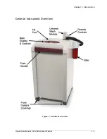
Page 15: ...Chapter 1 Introduction Operation Manual VIP 4400 Vessel Washer 1 7 General Instrument Overview Figure 1 Instrument Overview ...

Page 16: ...llation Operation Manual VIP 4400 Vessel Washer 2 1 2 Installation This chapter will describe the steps necessary to properly unpack and install the instrument Unpacking 2 2 System Setup 2 2 Installation Checkout 2 2 ...

Page 17: ...arger tank located in the back of the unit There is a black gasket on the right hand side Insert the overflow vessel into the hole in the gasket 3 Remove the wash handle shaft rinse if applicable from inside the instrument and close the top cover 4 Insert the wash handle into the holder located on the top cover 5 Insert the shaft rinse handle into the clip located on the right hand side panel 6 Re...

Page 18: ... Keypad 3 3 Filling the Rinse Tank 3 4 Using the Vessel Washer 3 5 Using the Manual Wash Feature 3 5 Using the Manual Drain Feature 3 6 Setting and Activating the Heater Optional 3 6 Using the Shaft Rinse Optional 3 7 Using the Visual Tank Level Indicators 3 8 Treating the Waste Tank Media 3 8 Emptying the Waste Tank 3 10 Priming the Waste Tank Drain Pump If Necessary 3 11 Emptying the Rinse Tank ...

Page 19: ...n will toggle the heater from activated or off the heater LED will toggle Holding the ON OFF SET will cause the display to flash the set temperature Using the Up or Down Arrow keys will change the set temperature Holding the ON OFF SET will return the unit to normal operation displaying the current tank temperature Waste Tank LEDs When the waste tank is full the FULL LED will be illuminated and wh...

Page 20: ... Manual Drain This button will drain all the media from the vessel for an unspecified period of time To stop this action the ABORT button must be pressed Manual Wash This button will both drain and wash the vessel for an unspecified time The wash will continue to run until the ABORT button is pressed This action is useful when needing to clean the vessel for an extended period of time Auto Wash Th...

Page 21: ...he rinse tank and lock the 2 front casters 2 Connect the tubing supplied with the unit to the quick connect fitting located on the top cover see Fill Port location in Figure 1 3 Connect the other end to the water source 4 Turn on the water source 5 When the tank is full the water source will automatically stop the unit is equipped with an internal water shutoff If the unit is powered on the FULL L...

Page 22: ...udible beep will be heard 6 Remove the UWM and insert into the next vessel 7 When all vessels have been cleaned return UWM into the top cover Figure 4 Universal Wash Module In order to remove most of the residual media from the wash cycle it may be necessary to remove the UWM from the vessel gently shake UWM above the vessel reinsert it in to the vessel and execute a manual drain Using the Manual ...

Page 23: ...or to cleaning the vessels This allows for a more efficient wash Pressing the ON OFF SET button will toggle the heater on and off 1 Ensure the unit is powered on 2 Press and hold the ON OFF SET button on the main keypad 3 The temperature display will begin blinking Using the Up or Down Arrow Keys change the blinking display to the desired set temperature 4 Press and hold the ON OFF SET to confirm ...

Page 24: ...ly raise the Dissolution Instrument s drive head 3 Remove the shaft rinse handle from the holder located on the right side panel 4 Position the shaft rinse spray nozzle close to the shaft 5 Press and hold the RUN button on the shaft rinse handle 6 Media will begin spraying out of the nozzle 7 Move the shaft rinse nozzle up and down the shaft and stirring apparatus while manually spinning the shaft...

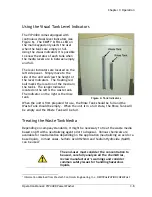
Page 25: ...the right is the rinse tank Figure 6 Tank Indicators When the unit is first prepared for use the Rinse Tank should be full and the Waste Tank should be empty When the unit is in a full state the Rinse Tank will be empty and the Waste Tank will be full Treating the Waste Tank Media Depending on company standards it might be necessary to treat the waste media based on pH with a neutralizing agent pr...

Page 26: ...OH Nitric Acid HNO3 Follow the steps below if necessary 1 Remove the Universal Wash Nozzle from the top cover 2 With a syringe or funnel dispense the neutralizing agent into the opening that houses the Universal Wash Nozzle Figure 7 Drain Beaker When viewing down the Universal Nozzle Holder hole a plastic beaker is visible See Figure 7 It is very important to ensure that the dispensing of the neut...

Page 27: ...nded to empty the Waste Tank everyday 1 Connect the supplied tubing to the quick connect fitting located on the rear cover See Figure 8 2 Place the other side outlet of this tubing into the waste containment area waste drum sink etc 3 Power the unit on 4 Press the Empty Waste Tank button located on the rear cover for 2 3 seconds to activate the waste pump 5 When the Waste Tank is empty the drainin...

Page 28: ...d 1 Disconnect the quick connect fitting located next to the filter housing See Figure 9 2 Connect the supplied tubing to the quick connect fitting located next to the filter housing 3 Press the Empty Rinse Tank button located on the rear cover for 2 3 seconds to activate the pump 4 When the Rinse Tank is empty the draining will automatically stop 5 If necessary press and hold the Empty Rinse Tank...

Page 29: ... filter head The bottle is located on the right side of the instrument just below the top cover 2 Empty the media in the bottle and clean the filter bottle 3 Unscrew the filter located on the shaft extending below the filter head 4 Thoroughly clean the filter mesh 5 Reinstall the filter by screwing it back onto the shaft The top of the filter should be flush with the top of the shaft threads Do no...

Page 30: ...ants antifoaming agents must be placed in the Waste Tank to avoid excessive foaming Antifoam AF is an example of an agent that can be used and is readily available from companies such as Spectrum Laboratory Products Inc Follow these steps prior to cleaning 1 Remove the Universal Wash Nozzle from the top cover 2 With a syringe or funnel dispense the antifoaming agent into the opening that houses th...

Page 31: ...er hole a plastic beaker is visible See Figure 11 It is very important to ensure that the dispensing of the antifoaming agent enters the plastic beaker located on top of the waste tank The bottom of the beaker contains a hole to allow media to drain into the waste bin The beaker can hold up to 100 mL of media ...

Page 32: ...intain the VIP 4400 Vessel Washer To ensure consistent performance a Preventive Maintenance PM Qualification should be conducted periodically Contact Distek for more information General Information 4 2 Cleaning the Tanks 4 2 Opening the Top Cover 4 3 Tubing Replacement 4 3 Cleaning the Water Inlet Valve Filter 4 4 Temperature Calibration 4 5 ...

Page 33: ...s Improper servicing or adjustment practice can cause equipment failure or serious physical injury This equipment must be adjusted and serviced by qualified electrical maintenance personnel who are familiar with the construction and operation of the equipment and the hazards involved Take diligent care during adjustment All exposed points on the control circuit boards are electrically hot with res...

Page 34: ...nel open the unit for servicing 1 Turn the unit power off and unplug the unit from the wall socket 2 Remove the two front screws located behind the handle 3 Flip open the top cover Tubing Replacement Due to the importance of properly connecting the internal tubing to the correct ports it is recommended to contact Distek if internal tubing replacement is necessary The external tubing that connects ...

Page 35: ... panel mount connector next to the filter 14 Close and screw down the top cover Cleaning the Water Inlet Valve Filter Dangerous voltages exist on the circuit boards when powered Disconnect AC power from the units while troubleshooting Be alert High voltage can cause serious or fatal injury The float valve located in the rinse tank is used to stop the flow of clean media into the tank while filling...

Page 36: ...low temperature range is 0 30ºC but should be performed at approximately 20ºC The high temperature range is 35 55ºC but should be performed at approximately 45ºC An external NIST traceable probe should be used to set the internal temperature probe Temperature calibration procedure low and high temperature Depending on the tank temperature the instrument will automatically detect whether to perform...

Page 37: ...ld the HEATER button The display will flash the current set temperature 13 Simultaneously press and hold HEATER UP and DOWN ARROW buttons The Heavy LED will begin flashing The system has automatically entered the high temperature calibration mode 14 Using the arrow keys enter the external probe s temperature and then click HEATER to accept the setting and exit calibration mode A short audile beep ...

Page 38: ...oting Operation Manual VIP 4400 Vessel Washer 5 1 5 Troubleshooting This chapter provides troubleshooting information to identify the most common problems and their solution Troubleshooting 5 2 Error Codes 5 3 Service 5 4 ...

Page 39: ...Disconnect AC power from the unit while troubleshooting Be alert High voltage can cause serious or fatal injury Table 4 Troubleshooting Symptom Possible Cause Possible Solution Waste Tank will not empty The pump sounds like it is running but media is not getting dispensed The pump has lost its prime Follow the step in Priming the Waste Tank Drain Pump If Necessary on page 3 11 to resolve this issu...

Page 40: ...ot heat The heater is not functioning properly Contact the Distek Service Department Error Codes In the event that an error occurs the Error LED will illuminate and the two digit error code will be displayed The following table describes the errors codes Table 5 Error Codes Error Code Problem Possible Solution 1 CPU error Contact the Distek Service Department 2 Internal RAM error Contact the Diste...

Page 41: ... the waste tank Both sensors are triggered Replace waste tank sensors 12 Heater error If the tank temperature is higher than 65ºC this error will be displayed Contact the Distek Service Department Service If you have a problem with the instrument or need parts information contact the Distek Service Department by e mail at support distekinc com or call our toll free number 888 234 7835 Items return...

Page 42: ...ow 3AG 1 4 x 1 25 250V 5A 5610 0368 Clear PVC Tubing 3 8 ID x 5 8 OD Visual Float Indicators 5610 9009 Clear PVC Tubing 1 2 ID x 3 4 OD 5610 9010 Clear PVC Tubing 5 8 ID x 7 8 OD 2800 0149 Drain Fill Tubing Assembly 3250 0157 Spray Nozzle 3250 0180 Suction Tip 6500 0012 1 Liter Wide Mouth Bottle 5720 0260 PVC Suction Line Strainer 40 Mesh 5720 0020 Water Valve Shutoff ...

Page 43: ...te should be wired in a 3 phase 4 wire configuration with an approximate load balancing among the phases In sites where many systems are being installed the number of systems wired to each phase should be balanced as much as possible 5 To minimize the risk of damage to a system from electrical system problems Verify that the power wiring configuration is proper If possible verify the current dissi...

Page 44: ...Appendix C CE Declaration of Conformity Operation Manual VIP 4400 Vessel Washer C 1 Appendix C CE Declaration of Conformity The VIP 4400 is currently undergoing CE and ETL testing ...

Reviews: