background image

Manuale di installazione e
manutenzione per
automazioni per cancelli
scorrevoli.

Installation and mainte-
nance  manual  for sliding
gate automatic system .

Manuel d'installation et
d'entretien pour
automatisme pour portails
coulissants

Montage und Wartungs-
handbuch für Schiebetore
Automatisierung

Manual de instalaciòn y
manutenciòn para
automatizaciòn de
cancelas de corredera.

CS 61E / CS 61

IP1580 30/06/99

Summary of Contents for CS 61

Page 1: ...nte nance manual for sliding gate automatic system Manuel d installation et d entretien pour automatisme pour portails coulissants Montage und Wartungs handbuch für Schiebetore Automatisierung Manual de instalaciòn y manutenciòn para automatizaciòn de cancelas de corredera CS 61E CS 61 IP1580 30 06 99 ...

Page 2: ...generales de securité page 16 Donnees tecniques page 17 Elements page 17 Installation page 17 Raccordement electriques CS61E page 18 Demarrage page 19 Raccordement electriques CS61 page 19 Entretien periodique page 19 Recherche pannes page 19 Instructions d utilisation page 20 Standard Montage pag 3 Abbildungen pag 4 5 Allgemeine Sicherheitshinweise pag 21 Technischen Daten pag 22 Verweis auf Abbi...

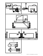
Page 3: ... P A IP1580 30 06 99 CS61 CS61E Fig 1 Impianto tipo Standard installation Installation type Standard Montage Instalaciòn tipo I UK F D E TX 4x0 5 mm RX 4x0 5 mm 4x0 5 mm 1 3 2 5 3 x 1 5 m m 2x1 5 mm 4 8 5 6 6 7 ...

Page 4: ...4 DITEC S P A IP1580 30 06 99 CS61 CS61E fig 2 200 95 20 315 200 100 110 275 fig 3 9 13 12 11 10 15 14 fig 4 fig 5 80 200 130 270 max 5 mm B D E F G min 30 ...

Page 5: ... P A IP1580 30 06 99 CS61 CS61E 2 3 fig 6 fig 7 fig 8 20 fig 9 fig 10 DIP1 OFF DIP1 ON H M 1 U W V NERO BLACK C 16 µF A BLU BLUE BIANCO WHITE NERO BLACK BLU BLUE BIANCO WHITE CS61 com FC1 11 FC2 12 COM 0 fig 11 ...

Page 6: ...rrect for the destination power requirements A multipolar isolation switch with minimum contact gaps of 3 mm must be included in the mains supply Check that upstream of the electrical installation there is an adequate differential switch and a suitable circuit breaker Ensure that the motorised door or gate has an earth terminal in accordance with the safety regulations in force The manufacturer of...

Page 7: ...tres 3 2 Fig 4 Lay a concrete foundation with buried anchoring brackets and the base plate making sure that it is pefectly level and smooth Allow for 80 mm between the plate axis and the rack B Route the cable ducts through the two holes in the middle of the plate 3 3 Fig 5 Open the release access door 11 loosen the screw that locks the carter and lift it Insert the ancoring feet G at the gear mot...

Page 8: ...ed REMOTE CONTROL STEP BY STEP It has the same function as the 1 5 control Parallel connection This model does not permit the running of two motors of automatic controls in parallel 4 2 Output and accessories 1 Accessories power supply 24V 0 15A nominal 0 3 A peak output 0 for powering of external accessories including gate state lamp 1 11 Lamp 24 V 1 5 W gate open with DIP1 ON closed gate lamp wi...

Page 9: ...ion of one of the safety devices is half the set time 5 5 Put RF in the position which ensures functioning and the safety of the user 5 6 After having set RF set the obstacle detection sensitivity with R1 5 7 Connect any accessories and check their function 5 8 Re fit the casing and make sure that the stop microswitch tripped by release door 11 is properly operating 6 ELECTRICAL CONNECTION CS61 Co...

Page 10: ...sed door or gate Keep remote control or any other control devices out of the reach of children in order to avoid possible involuntary activation of the motorised door or gate In case of breack down or malfunctioning of the product disconnect from mains do not attempt to repair or intervene directly and contact only qualified personnel Failure to comply with the above may create a situation of dang...

Reviews: