13
DITEC S.P.A - IP1580 30/06/99 - CS61/CS61E
WARNING:
Link up all N.C. contacts (if not used) by means of jumpers.
The terminal bearing the same number are equivalent.
ENGLISH
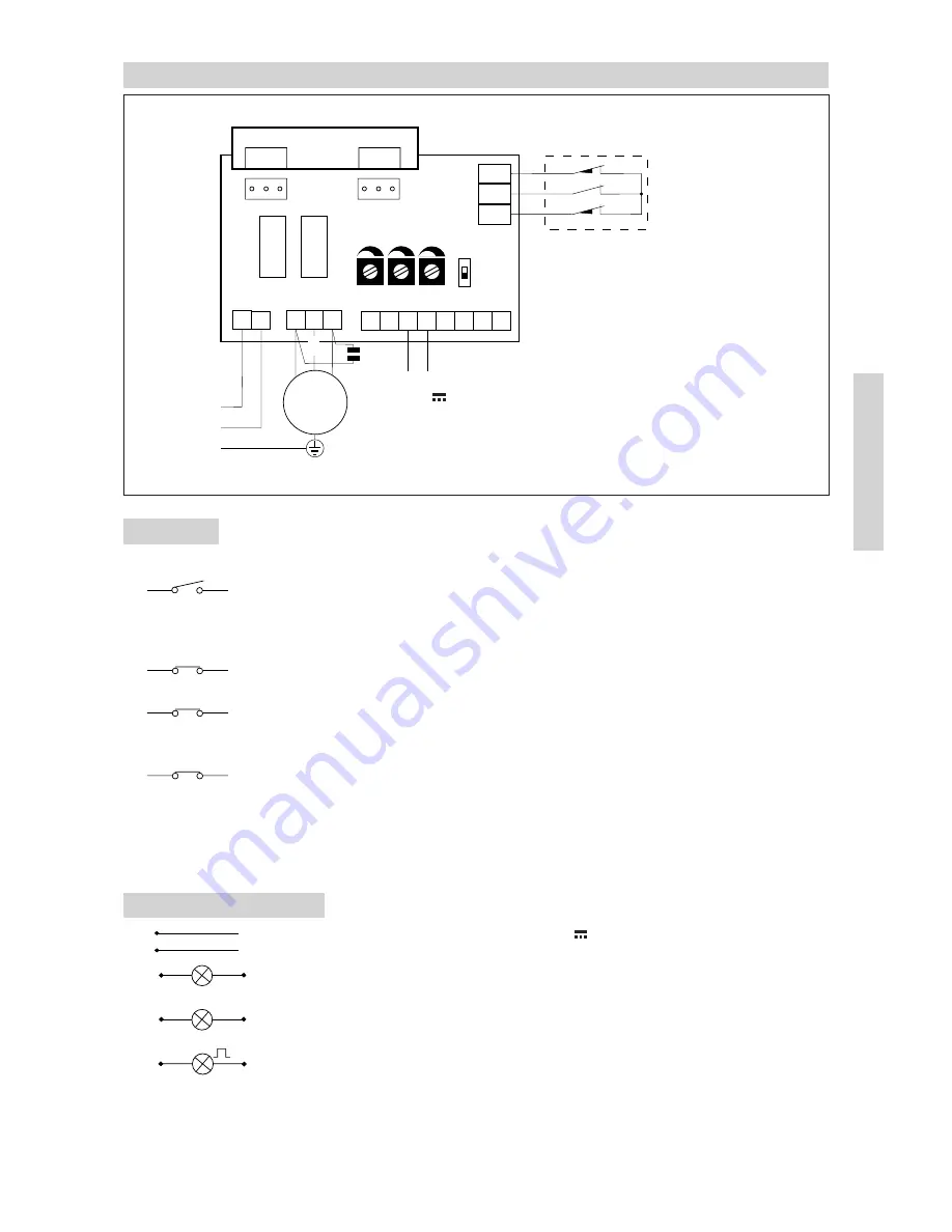
4. ELECTRICAL CONNECTIONS CS61E
4.1 Controls
CONTACT
FUNCTION
DESCRIPTION
1
5 (N.O.)
STEP BY STEP
With TC at maximum: “open-stop-close” sequence.
With TC not at maximum: “open-close/automatic
closure” sequence. The closing control can operate
when the gate is standing opened.
1
6 (N.C.)
STOP SAFETY
It stops and/or prevents any movement.
CONTACT
1
8 (N.C.)
REVERSAL SAFETY
Reverses movement (re-opens) during closing.
CONTACT
When door is not moving, inhibits all operation.
1
9 (N.C.)
EMERCENCY
By opening the 1-9 contact the gate stops or remains
STOP
still and the automatic closing is disabled.
REMOTE CONTROL
STEP BY STEP
It has the same function as the 1-5 control.
Parallel connection
This model does not permit the running of two motors
of automatic controls
in parallel.
4.2. Output and accessories
1
+
Accessories power supply. 24V / 0.15A (nominal) / 0.3 A (peak) output
0
-
for powering of external accessories including gate state lamp.
1
11
Lamp (24 V / 1.5 W) gate open with DIP1 ON, closed gate lamp with
DIP1 OFF.
1
12
Lamp (24 V / 1.5 W) gate close with DIP1 OFF, open gate lamp with
DIP1 ON.
W
N
Flashing light. 230 V~/ 100 W max. output. It is lighting during the opening
and closing operation. With automatic closure mode the flashing begins
3 s before the end of the setted time of TC, with TC lesser 3 s the flashing
lasts as long as the break time.
F1
F2
Q.E. D61
L N
U W V
12 11 0 1 5 6 8 9
230 V~
M
1 ~
FC2
FC1
COM
16 µF
RF TC R1
DIP1
Limit switch
Release micro
Limit switch
ON
OFF
+
-
24 V
/ 0.15 A
F1 = F5 A line
F2 = F315 mA accessories
CONTROL BOARD
com


