14
DITEC S.P.A - IP1580 30/06/99 - CS61/CS61E
ENGLISH
4.3 Setting and adjustments
TC - Automatic closure time. From 0 to 120 s, with TC from 0 to 3/4 turn. The counting begins:
- at the end of the opening operation and lasts as long as the time set on the TC trimmer;
- after a safety device has operated (1-6 / 1-8) and lasts half the time set on the TC.
TC at maximum disable the automatic closure. Warning: the position of TC (which enables or disables automatic
closing ) also selects the function of control 1-5.
RF - Power adjustment. Setting of RF from min to max selects min to max power. The motor always starts up
at max power and after 1 s switches over to the power set via RF.
R1 - Obstacle detection adjustment. The electric board is fitted with a safety device which, in case of an
obstacle being detected, causes the gate to stop moving when it is opening and to reverse movement when it is
closing. With trimmer R1 at minimum there is maximum sensitivity. With R1 at maximum the function is cut out.
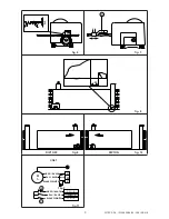
DIP1 - Selection of movement direction OFF = opening toward the right, ON = opening toward the left (see
fig. 9 and 10).
5. STARTING UP
WARNING: the operations regarding point 5.2 are without safety devices.
the trimmer can only be adjusted with gate not moving (RF excluded).
5.1. Set TC, RF and R1 at maximum. Short circuit the safety devices and the stop device. Select desired
movement direction by means of DIP1 (see fig. 9 and 10).
5.2. Power and check the gate functions correctly with a sequence of step-by-step commands. Check the action
of the limit switches.
5.3. Remove the jumpers and connect the safety devices (1-6 and 1-8) and the stop (1-9). Check their function.
5.4. Adjust the automatic closure with TC. Warning: the automatic closure time after the operation of one of
the safety devices is half the set time.
5.5. Put RF in the position which ensures functioning and the safety of the user.
5.6. After having set RF, set the obstacle detection sensitivity with R1.
5.7. Connect any accessories and check their function.
5.8. Re-fit the casing and make sure that the stop microswitch tripped by release door 11 is properly operating.
6. ELECTRICAL CONNECTION CS61
Connect the motor and limit switches to the control panel as in figure 11. A and C refer to opening and clos-
ing limit switch.
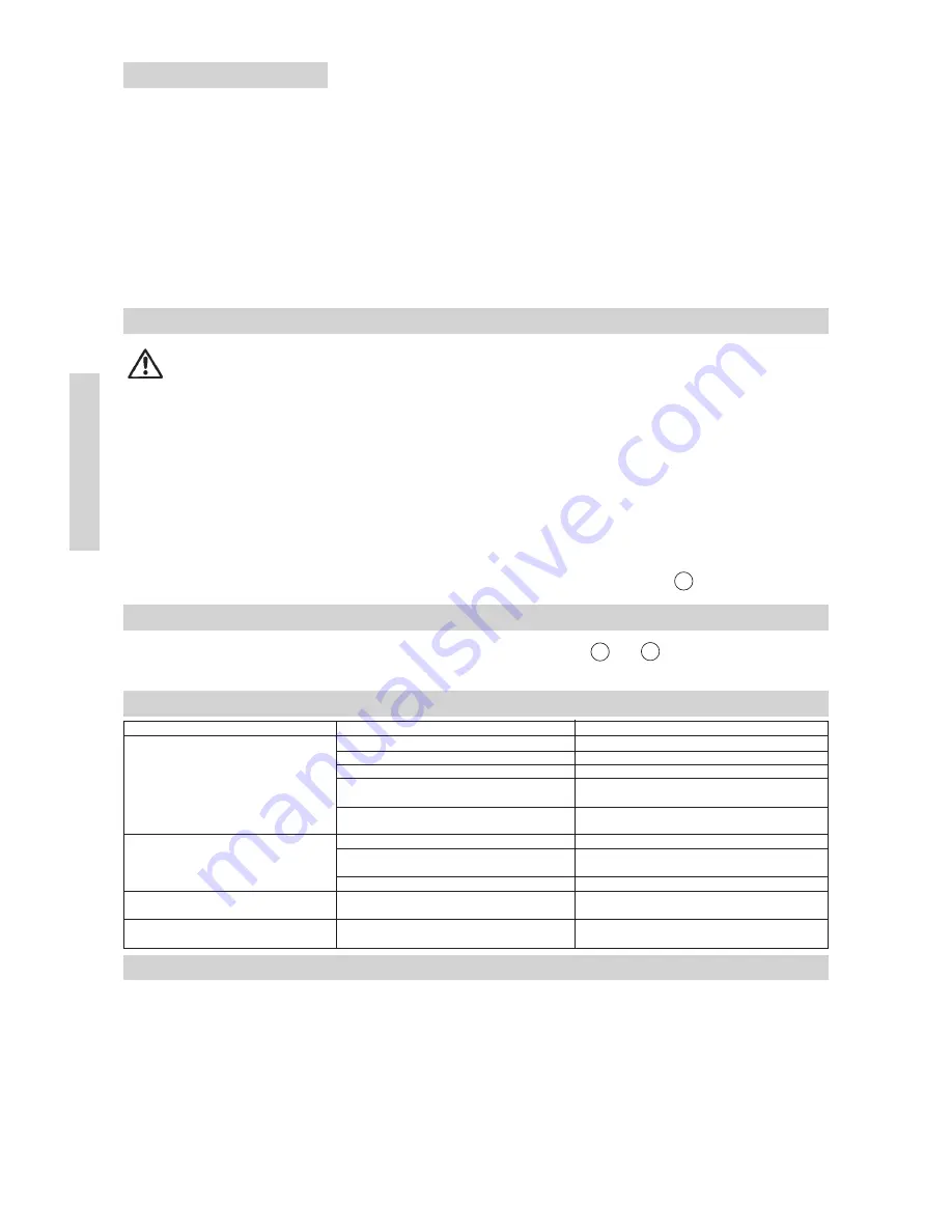
7. TROUBLE SHOOTING
8. MAINTENANCE PROGRAM (each 6 month)
Power off (230 V~ mains and batteries, if installed)
- Check gate/gear motor alignment and the distance (2-3 mm) between the mouth of the pinion and the crest of the rack.
- Clean the wheel slideways, the rack and the pinion of the geared motor.
Power on (230 V~ mains and batteries)
- Check the functioning of the limit switches (the gate must come to a halt ~ 20 mm before the stop)
- Check the power adjustments.
- Check the operation of all command and safety functions (photocells).
ATTENTION: For spare parts, see the spares price list.
PROBLEM
Gate fails to open and close.
Gate opens but fails to close.
External safeties fail to trigger.
Flashing light not work.
POSSIBLE CAUSE
Power failure.
F1/F2 fuse blown.
Safety contacts open.
Geared motor released.
Radio control not working.
Safety contacts open.
Photocells activated.
Automatic closure not working.
Incorrect wiring between photocells and the
Electric Board.
Bulb blown.
REMEDY
Check for power supply from mains.
Change fuse.
Check terminals 6, 8 and 9 in the E. B.
Check that release door is locked and that
release microswitch is pressed.
Check for proper installation and activation of
the radio device (TX and RX).
Check terminal 8 of the E.B.
Check that photocells are clean and properly
working
Check that TC trimmer is not set to maximum.
Connect N.C. safety contact in series and
remove any jumpers.
Replace with a 230 V bulb.


