4
LAN4 - IP1719
AVVERTENZE GENERALI PER LA SICUREZZA
Il presente manuale di installazione è rivolto esclusivamente a personale pro-
fessionalmente competente. Leggere attentamente le istruzioni prima di iniziare
l’installazione del prodotto. Una errata installazione può essere fonte di pericolo
I materiali dell’imballaggio (plastica, polistirolo, ecc.) non vanno dispersi nell’am-
biente e non devono essere lasciati alla portata dei bambini in quanto potenziali
fonti di pericolo. Prima di iniziare l’installazione verificare l’integrità del prodotto.
Per l’eventuale riparazione o sostituzione dei prodotti dovranno essere utilizzati
esclusivamente ricambi originali. E’ necessario conservare queste istruzioni e
trasmetterle ad eventuali subentranti nell’uso dell’impianto.
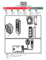
Il sistema di comando a codice LAN4S (scheda decoder) e LAN4T-LAN4M (tastiera
da esterno) permette l’apertura di porte e cancelli motorizzati (e/o il comando di
serrature elettriche) mediante la digitazione di un codice.
1. INSTALLAZIONE
Inserire la scheda decoder LAN4S nella sede per ricevitore radio all’interno del quad-
ro di comando dell’automazione (oppure utilizzare CONT1 per installazioni esterne).
Fissare la tastiera LAN4T-LAN4M in modo da avere la completa visuale della
porta o cancello automatico.
2. COLLEGAMENTI ELETTRICI
Collegare la tastiera al decoder LAN4S come in fig. 2.
E’ indifferente collegare al decoder 1 o 2 tastiere.
Attenzione: le morsettiere del decoder e delle tastiere non hanno polarità pertanto
il collegamento è indifferente.
Non passare i fili di collegamento delle tastiere alla scheda decoder nelle immediate
vicinanze di cavi di rete o di potenza.
In fig. 3 sono indicati i collegamenti per l’apertura di porte automatiche.
In fig. 4 sono indicati i collegamenti per l’apertura/chiusura di porte automatiche
con selettore di funzioni in posizione notte.
3. INSTALLAZIONE SECONDA TASTIERA
Eseguire i collegamenti come indicato.
Per abilitare il funzionamento della seconda tastiera premere brevemente il tasto
PRG presente sul decoder LAN4S.
4. CODIFICA DI OUT1 E OUT2
Il dip-switch DIP1 permette di abilitare o disabilitare la funzione di modifica codici.
DIP1=ON
modifica codici disabilitata
DIP1=OFF
modifica codici abilitata
- La lunghezza del codice deve essere di 4÷8 cifre.
- Ogni cifra deve essere digitata entro 3 s dalla precedente in caso contrario il
codice non sarà considerato valido.
- Le cifre con lo stesso tasto coincidono (1=2, 4=5, 7=8).
- Alla prima accensione sono attivi i codici di fabbrica.
Alcuni codici potrebbero non essere considerati validi. Esempi di codici non validi:
- 1111 se su OUT2 è memorizzato il codice 11113;
- 13467890 se su OUT2 è memorizzato il codice 1346;
- 2222 quando su OUT2 è memorizzato il codice 1111;
- 123 perché il numero di cifre è inferiore al limite minimo di 4 cifre;
- 1234567890 perché il numero di cifre è superiore al limite massimo di 8 cifre.
OUT1 (DIP1=OFF)
- Digitare il codice memorizzato (es: 0000)
- Premere per 5 s il tasto [*]
- Dopo 3 brevi segnali acustici digitare il nuovo codice entro 60 s (es: 12345)
- Premere il tasto [*]
- La corretta memorizzazione è confermata da un segnale acustico.
OUT2 (DIP1=OFF)
- Digitare il codice memorizzato (es: 1111)
- Premere per 5 s il tasto [*]
- Dopo 3 brevi segnali acustici digitare il nuovo codice entro 60 s (es: 54321)
- Premere il tasto [*]
- La corretta memorizzazione è confermata da un segnale acustico.
5. RIPRISTINO CODICI DI FABBRICA
Per ripristinare le codifiche iniziali del decoder LAN4S (codice OUT1=“0000”;
codice OUT2=”1111”) premere e tenere premuto il tasto PRG fino all’accensione
del LED. Rilasciare e, entro 5 s, premere nuovamente il tasto PRG.
6. FUNZIONAMENTO
Per attivare i contatti di uscita digitare i relativi codici predefiniti o personalizzati.
In caso di tentata manomissione, dopo 25 digitazioni errate effettuate in un inter-
vallo di 2 min, la tastiera si blocca per 2 min. In queste condizioni la tastiera non
riconosce alcun codice e non emette segnalazioni acustiche. Scaduto questo
intervallo di tempo, la tastiera ritorna nello stato di attesa.
N.B.: il LED lampeggiante segnala un errore di connessione.
Selezionare lo stato di DIP2 secondo le esigenze:
DIP2=OFF
attivazione uscite 1 s
DIP2=ON
attivazione uscite 10 s (consigliato per l’apertura e la
chiusura di porte automatiche in modalità “notte” - fig.4)
GB
I
GENERAL SAFETY PRECAUTIONS
This installation manual is intended for professionally competent personnel
only. Read the instructions carefully before installing the product. The incorrect
installation may cause danger. Packaging materials (plastic, polystyrene, etc.)
should not be discarded in the environment or left within reach of children, as
these are a potential source of danger. Before installing the product, make sure
it is in perfect condition. Use original spare parts only for repairs or replacements
of products. These instruction must be kept and forwarded to all possible future
users of the system.
The LAN4S (decoder card) and LAN4T-LAN4M (external keypad) coded control
system allows motorised doors and gates to be opened (and/or the control of
electrical locks) by keying in a code.
1. INSTALLATION
Insert the LAN4S decoder card in the radio receiver housing inside the control
panel of the automation (or use CONT1 for external installations).
Mount the LAN4T-LAN4M keyboard so as to have a full view of the automatic
door or gate.
2. ELECTRICAL CONNECTIONS
Connect the keypad to the LAN4S decoder, as shown in fig. 2.
1 or 2 keypads can be connected to the decoder without making any difference.
Attention: the terminal boards of the decoder and the keypads have no polarity so
the connection can be made either way.
Do not pass the wires connecting the keypad to the decoder card in the immediate
vicinity of mains or power supply cables.
Fig.3 shows the connections for the opening of automatic doors.
Fig.4 shows the connections for the opening/closing of automatic doors with the
functions selector in the night-time position.
3. SECOND KEYPAD INSTALLATION
Make the connections as indicated.
To activate the second keypad, briefly press the PRG key on the LAN4S de-
coder.
4. OUT1 AND OUT2 CODING
The DIP1 dip-switch allows you to activate or deactivate the code modification function.
DIP1=ON
code modification disabled
DIP1=OFF
code modification enabled
- The length of the code must be 4÷8 figures.
- Each figure must be keyed in within 3 s of the previous one, or else the code
will not be considered valid.
- The figures with the same key coincide (1=2, 4=5, 7=8).
- At the first start, the factory codes are active.
Some codes may not be considered valid. Examples of invalid codes:
- 1111 if the code 11113 is stored on OUT2;
- 13467890 if the code 1346 is stored on OUT2;
- 2222 if the code 1111 is stored on OUT2;
- 123 because the number of figures is less than the minimum limit of 4 figures;
- 1234567890 because the number of figures is more than the maximum limit of
8 figures.
OUT1 (DIP1=OFF)
- Key in the code stored (e.g. 0000)
- Press the key [*] for 5s
- After 3 brief acoustic signals, key in the new code within 60s (e.g. 12345)
- Press the key [*]
- The correct storage is confirmed by an acoustic signal.
OUT2 (DIP1=OFF)
- Key in the code stored (e.g. 1111)
- Press the key [*] for 5s
- After 3 brief acoustic signals, key in the new code within 60s (e.g. 54321)
- Press the key [*]
- The correct storage is confirmed by an acoustic signal.
5. RESET OF FACTORY CODES
To reset the original codes of the LAN4S decoder (code OUT1=“0000”; code
OUT2=”1111”), keep the PRG key pressed until the LED switches on. Release it,
then press again within 5 s.
6. OPERATION
To activate the output contacts, key in the relative predefined or personalised codes.
In the event of tampering, after 25 incorrect attempts within a space of 2 min, the
keypad will block for 2 min. In these conditions, the keypad does not recognise
any code and does not emit acoustic signals. After this time lapse, the keypad
returns to the standby status.
Note: the flashing LED indicates a connection error.
Select the status of DIP2 according to the requirements:
DIP2=OFF
activation of outputs 1 s
DIP2=ON
activation of outputs 10s (recommended for the opening
and closing of automatic doors in “night-time” mode - fig.4)


