14
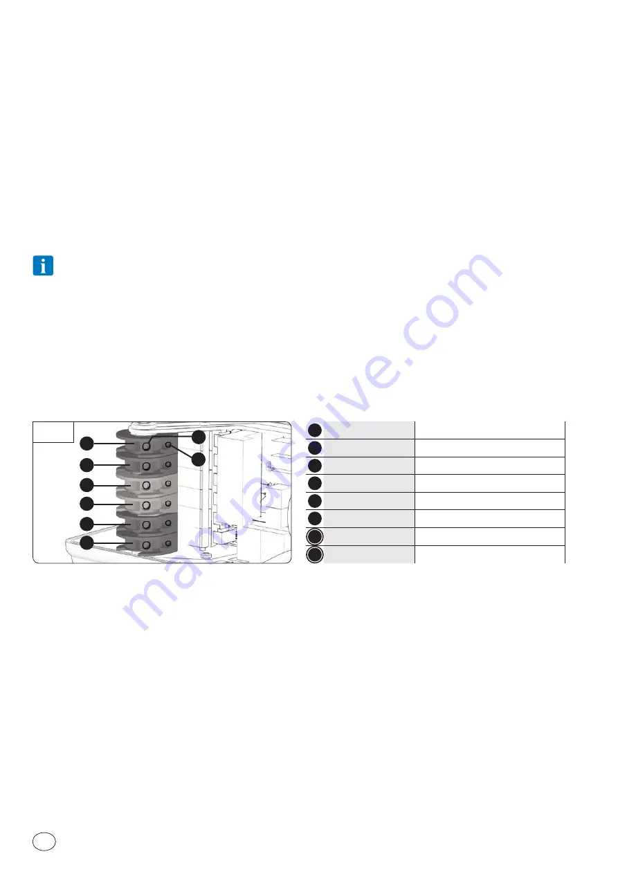
IP2361
EN
1
GREEN
UP Cam
2
GREEN
DOWN Cam
3
RED
SECURITY UP Cam
4
RED
SECURITY DOWN Cam
5
YELLOW
AUXILIARY CONTROL cam 1
6
YELLOW
AUXILIARY CONTROL cam 2
A
Fastening screws
B
Fine adjustment screw
Fig. 7A
1
A
2
B
3
4
5
6
7. LIMIT SWITCH SETTING
7.1 ABSOLUTE ENCODER LIMIT SWITCH SETTING - Ditec NRG100TXE, NRG100TRE AND
NRG140TXE
In Ditec NRG100TXE, NRG100TRE e NRG140TXE such tool is integrated in the limit switch that sends the commands to the external
control. Through a telegram of pulses the tool determines and communicates to the electronic controls what the position of the
sectional door is and consequently allows to perform the various assigned commands.
The data connection cable (with AMP connector) must be inserted in its place on the encoder
L
(Fig. 6C) and at the other end, in the
control unit. Follow the control instructions and use the external electromechanical control panel in order to determine the up and
down limit switch position and of any other auxiliary control.
This limit switch has no microswitches blocking the sectional door in case the limits are overcome. The external control panel will
manage the security of the system.
7.2 MECHANICAL LIMIT SWITCH SETTING - Ditec NRG100TXF
The 6 cams send to a control unit the signals necessary to know what is the position of the sectional door and execute the various
assigned commands accordingly.
The cams function is highlighted by their color (Fig. 7A): 2 green cams for the principal ones (up and down), 2 red cams for security,
2 additional yellow cams for the auxiliary controls.
Check that the motor direction of rotation corresponds to the complementary limit switch, otherwise invert one of the 3
phases of the 400 V
~
supply.
For the limit switch adjustment use the Allen key 3mm and proceed as follows:
1. Close the door in down limit position, release the
A
screw of the
Down cam
, turn the cam till it reaches the microswitch pin, then
tighten the
A
screw.
2. Tune the setting by the
B
screw of the
Down cam
till the microswitch is activated.
3. Open the door till the microswitch is free and then close it again.
4. Check and eventually tune the down limit through the
B
screw of the
Down cam
.
5. With the door in its closing position, set the safety down limit switch by releasing the
A
screw of the
safety Down cam
and turning
it till it reaches the microswitch pin (but without activating it), then screw it again. The safety limit switch enables to stop the door,
without any damage, in the case that the supply phases are reversed. In case it is activated, the control unit stops electrically the
motor and no operation will be possible until the protection is removed.
6. After having activated the sectional door until the upper limit, adjust the
Up cam
and the safety
Up cam
in the same way you have
done with the
Down
and security
Down cams
.
8. ROUTINE MAINTENANCE PLAN
Perform the following operations and checks every 6 months according to intensity of use of the automation.
Disconnect the power supply 400 V~:
- Lubrication of mechanical parts must be performed with door down.
- Make sure that cable and spring breakage device is in perfect working order.
- Check lift-cable wear.
- Make sure that the cables run smoothly in the drums.
- Periodically grease the hinges, ball-bearings, wheel pins, and torsional springs.
- Check for any obstacles that may hinder the wheels from properly running in the guides.
- To check the correct balancing of the sectional automation.
- Make sure that the overhead sliding structure is firmly fastened to the ceiling and perfectly free from any defects, bending or buckling.
- Make sure that there are no loose bolts or screws.
- Absolutely avoid making any changes to the hoisting and/or sliding system.
Connect the power supply (400 V~) and check that:
- Limit switches are working properly;
- All control and safety functions are in good working order.


