background image

 15

DITEC S.P.A - IP1597 - UP4EHS
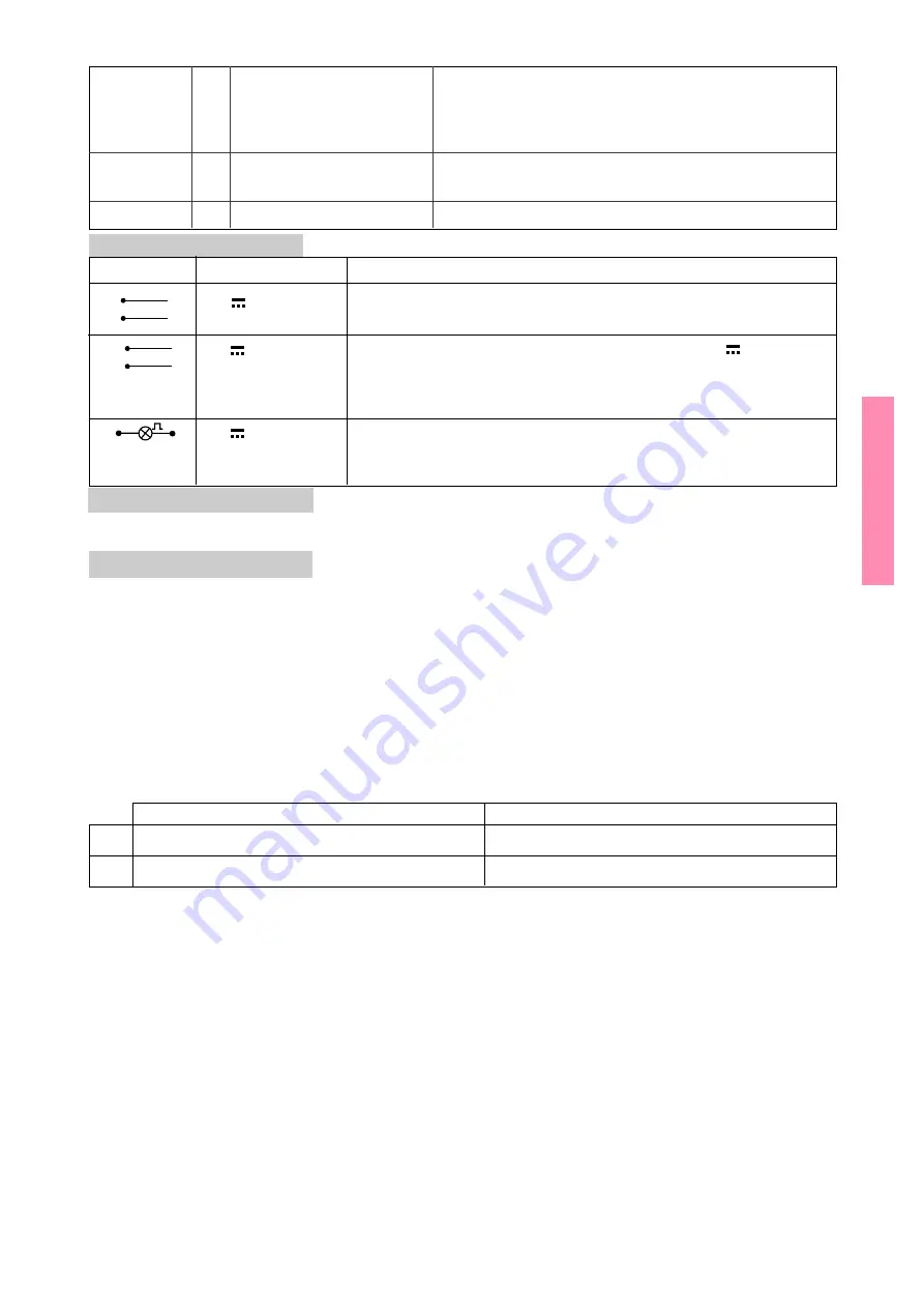
OPEN

N.O. STEP BY STEP /

This is the seat for the coupling of the radio receiver.
The remote control function is select by means of DIP1.

SAFETY

N.C. REVERSAL SAFETY CONTROL It has the same function as the 1-8 control.

4.3 Solar pannels connection

Use the SOLARP kit, which contains two solar cells of 12V/14W, together with the SOLARKS kit for mounting
the cells on a mast. Please observe the corresponding instructions.

4.4 Setting and adjustments

TC - Automatic closure time.  From 0 to 120 s. The counting begins:
- at the end of the opening operation and lasts as long as the time set on the TC trimmer;
- after a safety device has operated (1-8) and lasts half the time set on the TC.
With 1-2 or 1-9 open, automatic closing is disabled. Closing 1-2 re-enables automatic closing. If disabled from
1-9, automatic closing is once again enabled, by contacts 1-9 being reclosed, only after an open command is
given
.
VM - Movement speed adjustment. The VM trimmer adjusts the speed of the opening movement. The closing
speed is 40% of that set in the opening phase. Before the stop position there is a braking operation both in the
opening and in the closing phase.
R1 - Obstacle detection adjustment. The electric board is fitted with a safety device which, in case of an
obstacle being detected, causes the gate to stop moving when it is opening and to reverse movement when it is
closing. With trimmer R1 at minimum there is maximum sensitivity. With R1 at maximum the function is cut out.

Parallel connection of automatic controls (fig. 12) - Two motors A and B in parallel may be controlled by
wiring up as shown in the figure 2 (Diodes 1N4007 not provided).
Bearing in mind that terminals 0 and 5 of the two boards are not to be connected. For automatic closing by both
motors, proceed as follows:
- make a jumper between 1 and 2 in both A and B;
- set TC to the same value on both A and B.
RESTART -  Manual battery connection.
E.B. in standby status. Normally the Electric Board is in standby: electric energy consumption is reduced to a
minimum, and only the management and charge of the batteries, the radio and output 30 (common for N.O.
contacts) are active. In this situation output 1 is not enabled and the safety devices are not powered.
E.B. in active status. When the E.B. receives a command, it switches from the standby status to the active one.
In this situation the electric board is both powered and operational (also output 1 is enabled). The execution of
the command is interrupted for 300 ms so that the E.B. is enabled to read the inputs of the safety devices.

DIP1

DIP2

OFF

ON

Radio control selector = 30-5

Radio control selector = 30-3

Selection of movement direction = right opening Selection of movement direction = left opening

4.2   Output and accessories

1

+

Accessories power supply. Output for power external accessories.

0

-

Attention: this output is enabled when the E.B. is in the active status only.

30

+

Controls accessories power supply. Connect the 24V

 power supply

0

-

of the control devices (contacts: 30-3, 30-4 and 30-5) to output 0-30.
It is recommended that the accessories, which are powered at all
times, be as few as possible and of the low consumption type.

0

14

Flashing light. It is activated during the opening and closing operation.
For an automatic closure with a set time greater than 1.5 s, the flashing
begins 3 s before the closing operation.

OPEN

KEY
RELEASE

N.C.

Contact is activated by the barrier unlocking key. With the barrier
unlocked: line power supply and battery disconnected. On
switching on again (barrier locked), the first manoeuvre is carried
out with acquisition of the striking heights.

STOP

Value

Description

Output

24V   / 0.3 A (nominal)
              0.5 A (peak)

24V 

24V 

 / 25W

ENGLISH

Summary of Contents for UP4EHS

Page 1: ...llation et d entretien pour barri re lectrom canique Montage und Wartungs handbuch f r E l e k t r o m e c h a n i s c h e Torschranke Manual de instalaci n y manutenci n para barrera electromec nica...

Page 2: ...P4EHS 4x0 5 mm 4 UP AF SOLARP SOLARKS 2x1 5 mm RX 4x0 5 mm RX 4x0 5 mm 1 6 3 6 2 5 2x1 5 mm TX 4x0 5 mm 6 TX 4x0 5 mm Impianto tipo Standard installation Installation type Standard Montage Instalaci n...

Page 3: ...3 DITEC S P A IP1597 UP4EHS 270 245 182 1000 905 150 180 220 110 9 7 10 8 11 15 16 14 18 17 15 13 12 20 19 Fig 2 Fig 3 Fig 4 50 12 5...

Page 4: ...4 DITEC S P A IP1597 UP4EHS 21 16 22 23 21 16 22 23 14 DX SX UP4EHS DIP2 OFF UP4EHS DIP2 ON Fig 5 Fig 6 Fig 7 Fig 8 Fig 9 DX SX...

Page 5: ...power supply M P P BAT ENCODER Q E SolarUH RESTART OPEN SAFETY VM R1 TC F2 F3 M M 14 0 1 2 3 4 5 8 9 30 1 2 ON 12V 14W 12V 14W Nero Black Rosso Red 12 V 2 Ah 12 V 2 Ah KIT SOLARP KEY RELEASE 0 1 2 3 4...

Page 6: ...e le informazioni relative al funzionamento automatico manuale e di emergenza della porta o cancello motorizzati e consegnare all utilizzatore dell impianto le istruzioni d uso La manipolazione delle...

Page 7: ...e 30x100 luce netta 4500 mm UPGR Siepe in alluminio L 2000 mm UP4M Molla 5 UPC Confezione nr 10 catarinfrangenti rossi UP4MP Molla 3 5 UPAF Appoggio fisso UPSN Snodo per bracci UP4BC 4BL RHIPBG50 HIPB...

Page 8: ...centro o tendente verso l alto fig 6 Il sistema di leve che sostiene le molle per motivi di sicurezza costruito in modo da avere una posizione stabile con braccio completamente aperto o completamente...

Page 9: ...ntrambe le automazioni ponticellare 1 2 sia su A che su B impostare su A e su B lo stesso tempo di TC RESTART Inserimento manuale batteria Q E in stand by Il Q E normalmente in stand by il consumo di...

Page 10: ...e schiacciare il tasto RESTART e se il problema rimane verificare e ricaricare le batterie mediante carica batterie non di nostra fornitura In presenza di una sufficiente luce solare i pannelli inizia...

Page 11: ...o Non opporsi al moto della porta o cancello motorizzati poich pu causare situazioni di pericolo Non trattenere o appendersi all asta della barriera quando in movimento Non permettere ai bambini di gi...

Page 12: ...arm bands be worn when manipulating electronic parts MACHINERY DIRECTIVE Pursuant to Machinery Directive 98 37 CE the installer who motorises a door or gate has the same obligations as the manufacture...

Page 13: ...4M Spring 5 UPC Set of 10 red reflectors UP4MP Spring 3 5 UPAF Fixed bearing UPSN Articulated joint for UP4BC 4BL arms RHIPBG50 HIPBTA Border plug 3 INSTALLATION Unless otherwise specified all measure...

Page 14: ...system which supports the springs for safety purposes is constructed in order to have a stable position with arm completely open or completely closed even with the motor release Never use the motor f...

Page 15: ...ected For automatic closing by both motors proceed as follows make a jumper between 1 and 2 in both A and B set TC to the same value on both A and B RESTART Manual battery connection E B in standby st...

Page 16: ...press the RESTART button If the problem persists check battery and recharge if need be With adequate solar radiation the panels start charging the batteries and the electric panel latches on automatic...

Page 17: ...eld responsible for possible damage caused by improper erroneous or unresonable use Avoid operating in the proximity of the hinges or moving mechanical parts Do not enter the field of action of the mo...

Page 18: ...es L installateur doit fournir tous les renseignements concernant le fonctionement automatique manuel ou de secours de la porte ou du portail automatis s et remettre la notice d emploi l utilisateur...

Page 19: ...libre 4500 mm UPGR Herse aluminium L 2000 mm UP4M Ressort 5 UPC Serie de 10 bandes autocollantes UP4MP Ressort 3 5 reflechissantes rouges UPSN Articulation pour lisses UP4BC 4BL UPAF Appui fixe RHIPB...

Page 20: ...re ou tende vers le haut fig 6 Le syst me de leviers soutenant les ressorts pour des raisons de s curit est r alis a fin d obtenir une position stable lorsque le bras est compl tement ouvert ou compl...

Page 21: ...ouverture qu la fermeture R1 Pouss e sur les obstacles L armoire lectrique est quip e d un dispositif de s curit qui arr te le mouvement en cas d obstacle pendant la manoeuvre d ouverture et inverse...

Page 22: ...touche RESTART et si le probl me persiste v rifier et recharger les batteries Si l nergie solaire est suffisante les panneaux commencent charger les batteries et l armoire lectrique se branche automat...

Page 23: ...automatis s puissent tre actionn s involontairement En cas de panne ou de mauvais fonctionnement du produit d brancher l interrupteur de secteur ae s abstenir de toute tentative de r paration ou d in...

Page 24: ...jeder Anlage sind die technischen Daten des Torantriebs gut sichtbar anzubringen Vor dem Netzanschlu ist sicherzustellen da die Daten auf dem Typenschild mit denen des Stromversorgungsnetzes bereinst...

Page 25: ...P4M Feder 5 UPC Packung anz 10 Rote R ckstrahler UP4MP Feder 3 5 UPAF Festlager UPSN Gelenk f r UP4BC 4BL Arme RHIPBG50 HIPBTA Profile Stopfen 3 MONTAGE Alle angegebenen Ma e werden in mm ausgedr ckt...

Page 26: ...em Zubeh r ausbalanciert oder nach oben gerichtet ist Abb 6 Das Hebelsystem das die Feder zur Sicherheit st tzt ist so konstruiert da bei ganz ge ffnetem oder geschlossenem ArmauchbeientsperrtemMotore...

Page 27: ...en nicht miteinander verbunden werden Falls die automatische Schlie ung beider Automatisierungen gew nscht ist Br cken Sie 1 2 sowohl auf A als auch B Stellen Sie auf A und B dieselbe Zeit TC ein REST...

Page 28: ...kt werden Sollte das Problem fortbestehen m ssen die Batterien berpr ft und nachgeladen werden Wenn ausreichend Sonnenstrahlung zur Verf gung steht beginnen die Zellen mit dem Laden der Batterien und...

Page 29: ...ln oder der Antriebsteile aufzuhalten W hrend des ffnens und Schlie ens nicht den Arbeitsbereich des elektrisch angetriebenen Tors betreten Die Bewegung des elektrisch angetriebenen Tors nicht aufhalt...

Page 30: ...ento autom tico manual y de emergencia de la puerta o verja motorizadas y entregar al usuario del equipo las instrucciones para el uso Proveerse de brazaletes conductores anti staticos conectados a ti...

Page 31: ...ular 30x100 paso libre 4500 mm UPGR Fald n de aluminio L 2000 mm UP4M Resorte 5 UPC Serie de 10 cat ptricos rojos UP4MP Resorte 3 5 UPAF Apoyo fijo UPSN Desataro para brazo UP4BC 4BL RHIPBG50 HIPBTA C...

Page 32: ...accesorios instalados o con tendencia para abrir fig 6 Elsistemadepalancasquesujetanlosresortes pormotivosdeseguridad est fabricadodemaneraque aldesbloquearlo elbrazoquedeparadocuandoenposici ntotalm...

Page 33: ...puentear 1 2 tanto sobre A como sobre B programar el mismo tiempo TC sobre A y sobre B RESTART Introducci n manual de la bater a Tablero el ctrico en posici n de espera stand by Normalmente el tablero...

Page 34: ...o 30 3 o 30 4 presionar la tecla RESTART y si el problema persiste controlar y cargar de nuevo las bater as Silaenerg asolaressuficiente lospanelesinicianacargarlasbater asyeltableroel ctricoseconecta...

Page 35: ...o entrar en el radio de acci n de la puerta o verja motorizada durante su movimiento No oporse al movimiento de la puerta motorizada puede ser peligroso No sujetar la varilla de la barrera y no colgar...

Page 36: ...DITEC S p A Via Mons Banfi 3 21042 Caronno P lla VA Italy Tel 39 02 963911 Fax 39 02 9650314 www ditec it CARONNO P LLA VA QUARTO D ALTINO VE ISO 9001 Cert n 0957 0...

Reviews: