


7
DITEC S.P.A - IP1597 - UP4EHS
IT
ALIANO
1. DATI TECNICI
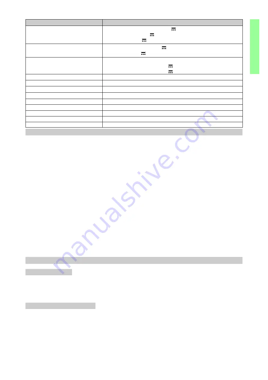
UP4EHS
Alimentazione batterie
Potenza motore
Tempo di apertura
Lunghezza asta (max)
Intermittenza
Grado di protezione
Temperatura
Peso
Alimentazione accessori (0-1)
Nominale
Picco
2x12 V / 2 Ah
2x12 V / 6.5 Ah (BATK2 opzionale)
2x12 V / 24÷50 Ah (non di nostra fornitura)
IP45
-15 °C / +50 °C
Autoconsumo Q.E.
8 mA
24 V / 0.3A
24 V / 0.5A
Pannelli solari
2x12 V / 14 W (SolarP)
2x12 V / 40÷100 W (non di nostra fornitura)
Coppia max.
100 W
45 Nm
1.5÷4 s / 90°
4700 mm
S2 = 7 min / S3 = 15%
40 kg
2. RIFERIMENTI ILLUSTRAZIONI E ACCESSORI
2.1 Riferimenti installazione tipo (fig. 1)
ATTENZIONE: nella realizzazione dell’impianto utilizzare esclusivamente accessori e dispositivi di si-
curezza DITEC.
[1] Radio
[4]
SolarP
[2] Lampeggiante
[5]
Barriera
[3] Selettore a chiave
[6]
Fotocellulle
2.2 Riferimenti barriera (fig. 3, 4 e 8)
[7] Base di fissaggio
[16]
Braccio leva
[8] Armadio
[17]
Attacco superiore molle
[9] Flangia porta asta
[18]
Molla
[10] Sblocco a chiave
[19]
Tirante regolazione molle
[11] Asta
[20]
Quadro elettrico
[12] Motoriduttore
[21]
Vite TE M12x110 zinc.
[13] Gruppo encoder
[22]
Staffa superiore attacco molla
[14] Leva di trasmissione
[23]
Dado autobloccante M12 zinc.
[15] Fermo meccanico interno
2.3
Accessori
-
UP4BC Braccio rettangolare (30x100) luce netta 3500 mm - UPAM
Appoggio mobile
-
UP4BL
Braccio rettangolare (30x100) luce netta 4500 mm - UPGR
Siepe in alluminio L= 2000 mm
-
UP4M
Molla Ø 5
- UPC Confezione nr. 10 catarinfrangenti rossi
-
UP4MP Molla Ø 3.5
- UPAF
Appoggio fisso
-
UPSN
Snodo per bracci UP4BC/4BL
- RHIPBTA Costa bassa+tappi
3. INSTALLAZIONE
Tutte le misure riportate sono espresse in mm, salvo diversa indicazione.
Installazione barriera
3.1
Predisporre una piazzola di cemento con annegate le zanche di ancoraggio e la piastra di base, che dovrà
essere in bolla e pulita. Infilare nei fori delle zanche di ancoraggio degli elementi in ferro o di altro materiale
per agganciare le zanche all’armatura di cemento. Far passare le canaline passacavi dal foro centrale
della piastra (fig. 3). Attenzione: assicurarsi della robustezza e la stabilità del fissaggio.
3.2
Fissare l’armadio.
Inversione del senso di apertura
Le barriere UP4EHS vengono fornite di serie destre. Per barriera destra si intende armadio montato a destra
vista lato ispezionabile. Per trasformare la barriera da destra a sinistra:
3.3 Smontare l’attacco superiore molla: vite [21] , aggancio molla [22] e dado [23] (fig. 8).
3.4 Ruotare di 90° il braccio leva (fig. 8).
3.5 Smontare la leva di trasmissione [14] dal braccio leva [16] e rimontarla nella stessa posizione assieme ai
particolari dell’attacco superiore molla: vite [21], aggancio molle [22] e dado [23] (fig. 8). ATTENZIONE:
utilizzare per l’assemblaggio la vite [21] e il dado [23] dell’attacco superiore molla.
3.6 Spostare il quadro elettrico e le batterie sul lato opposto.
3.7 Posizionare il DIP2 in ON (fig. 10).


