HEC-P6XXX User’s Manual
Document #: 2016002.1.pdf
PAGE 32 of 60
Divelbiss Corporation • 9778 Mt. Gilead Road • Fredericktown, Ohio 43019 • 1-800-245-2327 • www.divelbiss.com
HEC-P6XXX Features
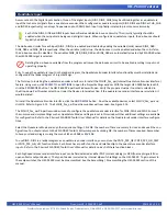
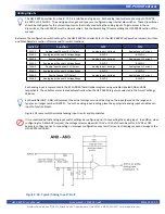
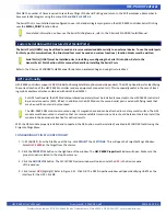
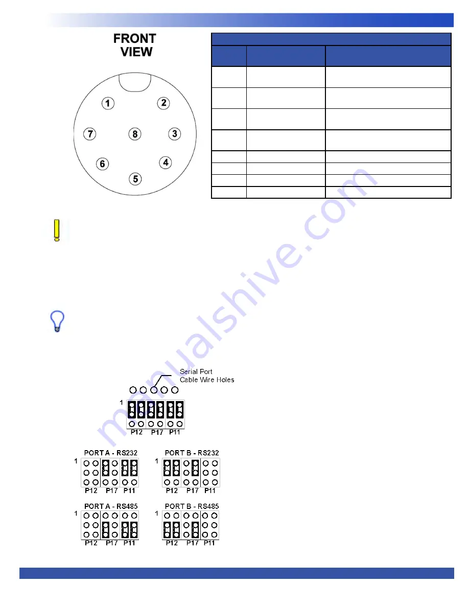
Figure 2.21 - General Purpose Serial Ports Cable Pin Out
Based on the need of RS232 or RS485, connector signal pin-out assembly will differ. Follow the pin-outs for the type of
interface required in Figure 2.21. The signal descriptions listed for each pin are based on the serial port jumper
configuration settings (see figure 2.22).
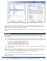
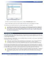
Next, using the jumper assignments, configure the jumpers for either RS232 or RS485 for each port. For jumper configurations, see
Figure 2.22.
To configure the jumpers, it will be necessary to dis-assemble the HEC-P6XXX controller. See the Assembling / Dis-assembling the
HEC-P6XXX section of this manual.
When using RS485, internal terminating resistors my be used by configuring the switches SW3-1 and SW3-2 for UART2 and
UART3 respectively. When SW3-1 or SW3-2 are ON, the terminating resistor(s) are enabled. When SW3-1 or
SW3-2 are OFF, the terminating resistor(s) are disabled.
Refer to the
HEC-P6XXX Configuration Jumpers, Switches and Potentiometers
section of this manual for switch and jumper locations.
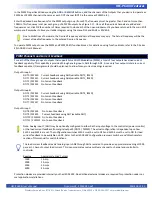
Serial Port Connect Pin Functions
Pin
Number
HEC-P6000
HEC-P6010 / HEC-P6200 / HEC-P6210
1
UART2: RS232 TXD /
RS485 A
UART2: RS232 TXD / RS485 A
2
UART2: RS232 RXD /
RS485 B
UART2: RS232 RXD / RS485 B
3
UART3: RS232 TXD /
RS485 A
UART2: RS232 TXD / RS485 A
4
UART3: RS232 RXD /
RS485 B
UART3: RS232 RXD / RS485 B
5
Gnd
Gnd
6
Gnd
Gnd
7
N/C
+5VDC (Power for GPS)
8
N/C
N/C
Figure 2.22- General Purpose Serial Ports Jumpers

