background image

HEC-P6XXX User’s Manual

Document #:  2016002.1.pdf

PAGE  53 of  60

Divelbiss Corporation • 9778 Mt. Gilead Road • Fredericktown, Ohio 43019 • 1-800-245-2327 • www.divelbiss.com

HEC-P6XXX Features

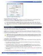
2.  Click the 

PROPERTIES

 button to the right side of the window. The 

HEC-P6000 Properties

 Window will open.  Make sure 

     the proper model is selected in the drop-down menu.

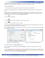
3.  Click the 

ADD DEVICE

 button. The

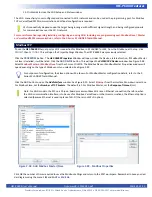
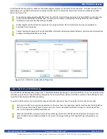
 PLCHIP-PXX Devices

 window will open. Locate the 

OptiCAN

 in the Devices pane    

      of this window.

4.  Click / select 

OptiCAN

 (highlight). Refer to Figure 2-53. 

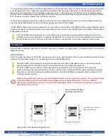
5.  Click 

OK

 . The 

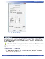
OptiCAN Properties

 Window will open. The settings in this dialog box will configure the OptiCAN network


Any OptiCAN network implementation will be dependent upon the actual applications needs and requirements. 


Knowledge of the OptiCAN network is required to configure the communications. Refer to the P-Series EZ LADDER Toolkit  


Manual for details on how the OptiCAN network functions, how to implement it and how to use it.

6. Enter the setup information for the OptiCAN network. Refer to Figure 2-54.


CAN Port:


Select the CAN Port to use the OptiCAN network on.


Node ID: 


Network address  (ID) for identify this equipment on the OptiCAN network.


Broadcast Rate:


Rate at which network registers are transmitted across the network (when 


based on interval). In milliseconds.


Send Heartbeat:


Check this box if this device is to send the network heartbeat (only one device 


per network).


Common Broadcast Registers:


Used to configure the Broadcast trigger of the Status and Error registers.


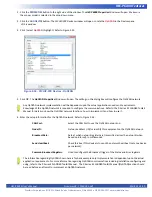
The information regarding OptiCAN shown here is for basic example only. Implementation is dependent upon the actual  


application requirements. For more information regarding OptiCAN communications including installation configuring and  


using, refer to the P-Series EZ LADDER Toolkit Manual.  The P-Series EZ LADDER Toolkit Manual (OptiCAN) section should  


be read before an attempt to implement an OptiCAN network.

Figure 2-53 - PLCHIP-PXX Devices - OptiCAN

Summary of Contents for HEC-P6 Series

Page 1: ...C P6010 HEC P6100 Divelbiss Corporation 9778 Mt Gilead Road Fredericktown Ohio 43019 Toll Free 1 800 245 2327 Web http www divelbiss com Email sales divelbiss com Based on P Series PLC on a ChipTM Technology Supports J1939 NMEA 2000 Networking and is VersaCloud M2M Enabled HEC P6110 HEC P6200 HEC P6210 ...

Page 2: ...sembling the HEC P6XXX 11 HEC P6XXX Configuration Jumpers Switches and Potentiometers 12 HEC P6XXX Features Programming Port 15 Status STS LED 16 Power PWR LED 16 Programmable LEDs I1 I2 16 User Programmable Switches 16 Input Power 16 Input Power Monitor 17 Mounting 18 Digital Inputs 18 Counter Inputs 19 Quadrature Input 24 Digital Outputs 25 Pulse Width Modulation Outputs 27 PWM Channel Load Curr...

Page 3: ...iss com Table of Contents CAN Networking Ports 37 FRAM Retentive Memory 40 EEPROM Memory ON CHIP 41 SD Card Memory 43 Ethernet Communications 44 WI FI Option 46 Modbus TCP 49 Structured Text Support 50 SAE J1939 NMEA 2000 50 OptiCAN Networking 52 Cellular Data Option 54 VersaCloud M2M Connectivity 56 Battery Backed up S RAM Memory 58 Specifications 59 ...

Page 4: ...Write a ladder diagram program Install the HEC 65XXX s Kernel if this is a new unit from the factory Download and run the program on the Controller Refer to the appropriate sections of this manual for details on the above items Getting Started WARNING The HEC P6XXX Controller as with other programmable controllers must not be used alone in applications which could be hazardous to personnel in the ...

Page 5: ...olders that represent the type of text to be entered by the user SMALL CAPS Used to show key sequences or actual buttons such as OK where the user clicks the OK button In addition the following symbols appear periodically in the left margin to call the readers attention to specific details in the text Warns the reader of a potential danger or hazard associated with certain actions Appears when the...

Page 6: ...uires VersaCloud M2M Telematics plan from Divelbiss with Nationwide coverage VersaCloud M2M requires VersaCloud M2M Portal account GPS Functionality using GPS Port and External GPS Module Supports Multiple Modbus Ports Internal Micro SD Card Dual CAN Ports Support Divelbiss OptiCAN SAE J1939 NMEA 2000 4 Analog Inputs Configured as 0 5VDC 0 10VDC or 0 20mADC 12 Bit Resolution 2 Analog Outputs 0 10V...

Page 7: ... the right side of the window The HEC P6000 Properties Window will open 3 Using the Drop down Part Number select box select the model of the HEC P6XXX Refer to Figure 1 2 With the model se lected the Devices pane will update with the currently selected features for the HEC P6XXX The ADD DEVICE button is used to install and configure additional features from those shown above such as Ports Real Tim...

Page 8: ...kernel before a ladder program can be downloaded If the kernel is already loaded this step is not required To upgrade a kernel see the P Series EZ LADDER Toolkit Manual THE HEC P6XXX WILL NOT FUNCTION UNLESS THIS STEP KERNEL LOADING IS COMPLETED To install the HEC P6XXX s kernel 1 Verify the target has been configured see Configuring the HEC P6XXX Target in EZ LADDER Toolkit 2 Connect the Programm...

Page 9: ...by default at C Program Files EZ Ladder Kernel Refer to Figure 1 3 The following are kernel names and descriptions File Name Description To be Used on Part number HEC_P6000 dat Kernel for HEC P6XXX HEC P6000 HEC P6010 HEC P6100 HEC P6110 HEC P6200 HEC P6210 8 Click the OPEN button to finish the kernel selection Make sure the correct kernel is chosen 9 Click the UPDATE TARGET button to install the ...

Page 10: ... assemblies may be purchased with the mating connectors pre wired with flying leads on one end HEC P100 HEC P110 HEC P120 and HEC P130 In addition to connectors and kits for standard wiring programming break out cable assemblies may be purchased HEC P910 The HEC P6000 front connector is a Deutsch DT13 48PABCD R015 that includes the keyed A B C and D connection points The following Deutsch connecto...

Page 11: ...OT Group C Digital Output 10 PWM 10 Pin 6 CAN Port 0 High Pin 6 DOT Group C Digital Output 11 PWM 11 Pin 7 CAN Port 1 Low Pin 7 DOT Group C Power Source Pin 8 CAN Port 1 High Pin 8 DOT Group D Digital Output 12 Pin 9 Analog Input 0 Signal Pin 9 DOT Group D Digital Output 13 Pin 10 Analog Input 1 Signal Pin 10 Analog Output 0 Pin 11 Digital Input 0 Counter Input 0 Pin 11 Analog Output 1 Pin 12 Digi...

Page 12: ...he enclosure 2 Slide the assembly completely into the enclosure until the locking latches are secure Please note If the HEC controller has an optional serial port make sure the serial board wires do not interfere or get caught on the enclosure s LED pipes clear plastic tubes CONNECTOR C GREEN CONNECTOR D BROWN Pin 1 Digital Input 2 Counter Input 2 Pin 1 DIN Group B Digital Input 12 Pin 2 Digital I...

Page 13: ...es and jumpers the HEC P6XXX must be dis assembled There are three 4 position slide switch blocks identified as SW1 SW3 and SW6 Each block contains 5 individual switches that are used to configure options When the switch is in the ON position it is closed In addition to the 4 5 position slide switch blocks 2 additional single switches are included SW4 and SW5 3 Position jumper blocks are also prov...

Page 14: ...C SW3 1 Serial Port A RS485 Termination Resistor Disabled Enabled SW3 2 Serial Port B RS485 Termination Resistor Disabled Enabled SW3 3 Analog Input Channel 7 Voltage Monitor Disabled Channel 7 Input Voltage SW3 4 Analog Input Channel 7 DOT9 Feedback Disabled Channel 7 DOT 9 Current SW3 5 User Programmable Switch 1 USER_IN1 Disabled Enabled SW4 CAN Port 0 Termination Resistor Disabled Enabled SW5 ...

Page 15: ...This section explains the Harsh Environment Controller HEC P6XXX hardware features options and information regarding EZ LADDER Toolkit for basic operation HEC P6XXX Features ...

Page 16: ...nnection from the PC to the HEC P6XXX controller The HEC P910 programming break out cable is an in line cable that allows for programming connections while still connecting the A connector and field devices as shown in Figure 2 2 It is strongly recommended to purchase this break out cable to use with a null modem cable Free technical support is not provided to trouble shoot communications problems...

Page 17: ...ndicators may be used to identify any number of condi tions of the HEC P6XXX controller or application User Programmable Switches The HEC P6XXX includes two user programmable switches that are accessed in the ladder diagram as digital inputs as USER_IN1 and USER_IN2 These boolean variables are automatically created when the HEC P6XXX target is selected These switches may be used to identify any fu...

Page 18: ... using variable AN7 AN7 is represented as an integer number and some logic must be added to the ladder diagram program to actually convert this raw analog value into volts Figure 2 4 is an example ladder diagram program to convert AN7 into volts AN7 Power Monitor Analog Input Integer Automatically created R_AN2 Variable used to store converted value of AN7 as a real variable type This is required ...

Page 19: ...t will operate from 8VDC to 32VDC DIN0 DIN2 variables DIN0 DIN2 These three 3 inputs may be used individually as digital inputs or as high speed counter inputs These inputs may be config ured as NPN or PNP inputs based on the configuration switches of SW1 1 SW1 2 and SW1 3 When configured as NPN these inputs are pulled to the input power voltage DIN3 DIN5 variables DIN3 DIN5 These three 3 inputs m...

Page 20: ...e coil is true the de bounce circuit is enabled and when the coil is false the de bounce circuit is disabled The variables DIN0_DEB DIN1_DEB and DIN2_DEB are automatically created by EZ LADDER when the HEC P6XXX target is selected Deleting the de bounce variables from the program will cause the de bounce circuit to be enabled This will reduce the frequency the input can read resulting in inputs no...

Page 21: ...9778 Mt Gilead Road Fredericktown Ohio 43019 1 800 245 2327 www divelbiss com HEC P6XXX Features Figure 2 6 Typical Digital Input Connections WWW DIVELBISS COM PWR I1 I2 STS HARSH ENVIRONMENT MODULE SERIAL Embedded PLC on a chip Fredericktown Ohio Patent 7 299 099 HEC P6XXX HEC P6XXX ...

Page 22: ... a 1 micro second resolution The TimerCounter function block in EZ LADDER provides additional controls for the timer counter functional ity When the Free Running Timer mode is selected no other configuration is required Refer to Figure 2 9 When the free running timer reaches it s upper counting limit it will wrap negative and begin counting toward zero This can be avoided by resetting the timer us...

Page 23: ...l configure for measuring period Refer to Figure 2 11 Click OK the number of times necessary to close and save all the configurations You should return to the EZ LADDER Tool kit s Edit workspace by clicking OK the number of times required Remember to Save your ladder diagram using the menu FILE and SAVE or SAVE AS To use DIN0 DIN3 in a ladder diagram you must use the TIMERCOUNTER function block Th...

Page 24: ...W1 1 SW1 2 and SW1 3 configures the counter timer type of input for DIN0 to DIN2 respectively When the switch is in the OFF position for the counter timer input the type is PNP When the switch is in the ON position for the counter timer the type is NPN Refer to the HEC P6XXX Configuration Jumpers Switches and Potentiometers section of this manual for switch loca tions Figure 2 12 represents the ti...

Page 25: ...h the target HEC P6000 selected still click the PROPERTIES button The HEC P6000 Properties Window will open Verify the proper actual part number is selected in the Drop down Part Number select box Under the Devices Internal section if the quadrature encoder interface were installed it would be listed To install the Quadrature Encoder Interface click the ADD DEVICE button From the available devices...

Page 26: ...s Pulse Width Modula tion PWM outputs The HEC P6XXX outputs are divided into three groups of four outputs each and one group of 2 outputs Three groups may operate as PWM or ON OFF outputs while the fourth group operates only as ON OFF outputs They are divided as follows Group A DOT0 DOT3 ON OFF or PWM variables DOT0 DOT3 Group B DOT4 DOT7 ON OFF or PWM variables DOT4 DOT7 Group C DOT8 DOT11 ON OFF...

Page 27: ...778 Mt Gilead Road Fredericktown Ohio 43019 1 800 245 2327 www divelbiss com HEC P6XXX Features Figure 2 15 Typical Digital Output Connections WWW DIVELBISS COM PWR I1 I2 STS HARSH ENVIRONMENT MODULE SERIAL Embedded PLC on a chip Fredericktown Ohio Patent 7 299 099 HEC P6XXX HEC P6XXX ...

Page 28: ...orrect output address DOT0 DOT15 from the provided drop down menu Pulse Width Modulation Outputs As previously noted the HEC P6XXX provides 14 digital outputs of which 12 may be configured individually and exclusively as either digital outputs or pulse width modulation outputs therefore each output may only be used once as either digital output or PWM output As the DOT and PWM outputs are one and ...

Page 29: ...e only four outputs total are current feedback capable I O assignments should be planned to allow for any current readings required Output Group A DOT0 PWM0 Current Feedback using AN5 variable DOT0_IFEED DOT1 PWM1 Current Feedback using AN6 variable DOT1_IFEED DOT2 PWM2 No Current Feedback DOT3 PWM3 No Current Feedback Output Group B DOT4 PWM4 Current Feedback using AN4 variable DOT4_IFEED DOT5 PW...

Page 30: ... AN0 AN3 will represent the actual voltage or current reading on the input based on the range and type as an integer number 0 4095 To use the analog input reading place the appropriate analog input variable as an input to function blocks Figure 2 18 represents the internal analog input circuits and dip switches It is recommended that analog input switch settings be configured prior to connecting t...

Page 31: ...cted in the Project Settings Window Each variable AOT0 AOT1 will control the actual output voltage per channel Changing the variable integer number of 0 4095 where 0 is approximately 0VDC and 4095 is 10VDC will result in the analog output voltage changing accordingly The analog outputs are factory calbirated but if the analog output is less than or greater than 10 00VDC if the variable is set to 4...

Page 32: ...battery disabled via a paper tab to conserve battery life You must enable the battery by removing the paper tab To gain access to paper tab the HEC P6XXX must be dis assembled See the Assembling Dis assembling the HEC P6XXX section of this manual Refer to the HEC P6XXX Configuration Jumpers Switches and Potentiometers section of this manual for the battery location Failure to enable the battery by...

Page 33: ...dis assemble the HEC P6XXX controller See the Assembling Dis assembling the HEC P6XXX section of this manual When using RS485 internal terminating resistors my be used by configuring the switches SW3 1 and SW3 2 for UART2 and UART3 respectively When SW3 1 or SW3 2 are ON the terminating resistor s are enabled When SW3 1 or SW3 2 are OFF the terminating resistor s are disabled Refer to the HEC P6XX...

Page 34: ...e 2 24 The RTS GPIO Pin is only used for RS485 If using RS485 click the drop down and select the only pin listed This is used for RS485 transmit control The Enable ST Buffers check box identifies to enable the structured text UART buffers This should only be used when using struc tured text for communications When enabled the buffer size must be completed When complete click OK the number of times...

Page 35: ...Select Modbus Master or Modbus Slave from the choices Click OK The Modbus Slave or Modbus Master Properties window will open depending on the type of Modbus port you selected See Figure 2 26 Click the ADD button to open the Add Interface win dow For Modbus Slave see Figure 2 27 Select UART from the Interface Drop down select box Set the Slave ID This should be the network ID for this HEC P6XXX con...

Page 36: ...nual for details on installing the Serial Ports To use the HEC P6XXX Serial Ports for Serial Printing in EZ LADDER Toolkit from the File Menu at the top click PROJECT then SET TINGS This will open the Project Settings Window The HEC P6XXX was previously selected Click the PROPERTIES button The HEC P6000 Properties Window will open Under the Devices Internal section if Serial Print is in stalled it...

Page 37: ...be mounted in a location that can receive satellite transmissions Care should be taken to test and install the module in the appropriate location for optimal results With the GPS module properly installed and connected the GPS option must be installed enabled in EZ LADDER Toolkit using the Project Settings Menu GPS Functionality Custom Serial Data with Structured Text Serial Ports The Serial Ports...

Page 38: ...implementing these networks refer to the P Series EZ LADDER Toolkit Manual The on board CAN ports are CAN0 and CAN1 To use the HEC P6XXX s CAN ports for OptiCAN it will be necessary to install the CAN Port s needed and configure certain parameters The CAN ports should be wired according to established practices for CAN networks Figure 2 32 illustrates typical CAN Port connections Ideally it is bes...

Page 39: ...s section if any CAN ports are installed they would be listed Click the ADD DEVICE button This will open the PLCHIP PXX Devices window Select either CAN0 or CAN 1 from the Devices pane See Figure 2 34 When the required CAN port has been selected click OK the number of times required to close the windows and return to the EDIT workspace Remember to Save your ladder diagram using the menu FILE and S...

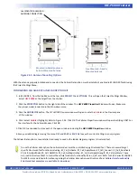
Page 40: ...WW DIVELBISS COM PWR I1 I2 STS HARSH ENVIRONMENT MODULE SERIAL Embedded PLCon a chip Fredericktown Ohio Patent 7 299 099 HEC P6XXX HEC P6XXX WWW DIVELBISS COM PWR I1 I2 STS HARSH ENVIRONMENT MODULE SERIAL Embedded PLCon a chip Fredericktown Ohio Patent 7 299 099 HEC P6XXX HEC P6XXX WWW DIVELBISS COM PWR I1 I2 STS HARSH ENVIRONMENT MODULE SERIAL Embedded PLCon a chip Fredericktown Ohio Patent 7 299...

Page 41: ...ive memory and 380 bytes of user memory FRAM not used for retentive may be used to store values using the EEPROM_READ and EEPROM_WRITE function blocks to memory and also is where variables configured as retentive are stored on loss of power CONFIGURING RETENTIVE MEMORY IN EZ LADDER TOOLKIT The retentive memory is installed automatically when the HEC P6XXX controller is selected in the Project Sett...

Page 42: ...e in terms of milliseconds and has limitations This EEPROM memory is located on the PLC on a Chip itself PLCHIP P13 51220 EEPROM memory should not be used in applications where the values are updated causing the stored value to update often such as a process variable While EEPROM memory has a long life repeated writing thousands of times can cause a memory location to fail EEPROM memory is more or...

Page 43: ...w be installed and return to the HEC P6000 Properties window 6 The PLCHIP_Pxx_eeprom is now shown in the Devices pane under the Internal heading Click OK to close the HEC P6000 Properties 7 Save your ladder diagram using the menu FILE and SAVE or SAVE AS to save the current settings in your program The PLCHIP_Pxx_eeprom on chip EEPROM is now installed in EZ LADDER Toolkit ladder diagram project an...

Page 44: ...install or update the kernel or EZ LADDER compiled project to the HEC P6XXX it must be config ured to do so This configuration must be done in the Bootloader screen The Bootloader screen will only operate if EZ LADDER is connected to an actual HEC P6XXX controller To Access the Bootloader 1 Verify the target has been configured see Configuring the HEC P6XXX Target in EZ LADDER Toolkit 2 Connect th...

Page 45: ...button to exit the bootloader and restart the HEC P6XXX Figure 2 39 HEC P6XXX Bootloader Figure 2 40 HEC P6XXX SD CARD OPTIONS Ethernet Communications Certain HEC P6XXX models supports Ethernet communications using an on board Ethernet port This port when enabled provides communications in 3 modes of operation The Ethernet port may be utilized as a programming port Modbus TCP master or slave port ...

Page 46: ... the kernel Choose GetStarted_HEC 5xxx dld 4 Click the Compile button 5 Click the Monitor button to change from the Edit to Monitor Mode 6 Click the Connect button to connect to the target 7 Using the menu click PROJECT then BOOTLOADER You may see a window momentarily while EZ LADDER connects to the HEC P6XXX s bootloader The Bootloader window will open See Figure 2 43 8 Click the TARGET OPTIONS b...

Page 47: ...p perspective as the processor of the HEC P6XXX controller it treats Wi Fi the same as Ethernet The Enable Wi Fi should be checked on Wi Fi models WI FI Option For HEC P6XXX models that support Wi Fi the Wi Fi connection is available for using Modbus TCP Programming Port or VersaCloud M2M Connectivity WI FI ANTENNA For Wi Fi supporting models of HEC P6XXX the unit ships with a loose packed antenna...

Page 48: ...ess network To configure for a Wi Fi network 1 Open a program or create a simple program and Compile the program if necessary 2 Change EZ LADDER to the Monitor mode by clicking the button 3 Make sure the target is connected to the computer and click the button to connect EZ LADDER Toolkit to the hardware the HEC P6XXX target 4 From the menu at the top select PROJECT then select WIFI SETUP Refer to...

Page 49: ...ction information that will be stored in the Access Point Settings 10 Click the soft reset button Item D This forces the Wi Fi connectivity to reset After the reset the HEC P6XXX should connect to the Wi Fi network 11 Click the refresh status button Item E The information under the Current Connection should update and show the network currently connected to 12 For information only other buttons in...

Page 50: ...lave from the choices Click OK The Modbus Slave or Modbus Master Properties window will open depending on the type of Modbus port you selected See Figure 2 49 For purposes of configuration the Slave option will be shown For Modbus Master configuration details refer to the P Series EZ LADDER Toolkit Manual Click the ADD button to open the Add Interface window See Figure 2 50 Select Ethernet from th...

Page 51: ... on language and implementation of structured text in an EZ LADDER project Structured text can be utilized for many features including custom se rial communciations needs creating custom advanced ladder diagram function blocks file system access SD Card Cellular data modem control and additional control of items such as Wi Fi VersaCloud and more SAE J1939 NMEA 2000 The HEC P6XXX controller support...

Page 52: ... ADD From the drop down menu select the CAN port to use must have been installed prior to this step Refer to Figure 2 52 All the configuration parameters for the J1939 NMEA 2000 communications must be configured here Refer to the P Series EZ LADDER Toolkit Manual for more in depth information on configuring and using SAE J1939 and NMEA 2000 7 Click OK to as needed to close each of the open windows...

Page 53: ...ng variables integer boolean real and timer The OptiCAN network provides communications with error and status moni toring of the connected devices As OptiCAN utilizes the CAN port a CAN port must be installed prior to the installation and configuration OptiCAN For CAN port installation refer to the CAN Networking Ports Section of this manual With a CAN port installed OptiCAN network must be instal...

Page 54: ... for details on how the OptiCAN network functions how to implement it and how to use it 6 Enter the setup information for the OptiCAN network Refer to Figure 2 54 CAN Port Select the CAN Port to use the OptiCAN network on Node ID Network address ID for identify this equipment on the OptiCAN network Broadcast Rate Rate at which network registers are transmitted across the network when based on inte...

Page 55: ...ly fees and data usage charges apply As data fees apply consideration should be made during the application ladder diagram program development to limit the amount and size of data to only what is required to reduce cost CELLULAR ANTENNA For Cellular connection supporting models of HEC P6XXX controller the unit ships with a loose packed antenna that must be in stalled before the Cellular connection...

Page 56: ...e interface for the Cellular Modem Click OK 5 Click OK to as needed to close each of the open windows including the HEC P6000 Properties window 6 Save your ladder diagram using the menu FILE and SAVE or SAVE AS to save the current settings in your program The Cellular Data option is now installed and ready to used in the ladder diagram program structured text To use the Cellular data option the ce...

Page 57: ... In addition to the HEC P6XXX communicating to local devices and systems using Modbus TCP Modbus Slave Modbus Master J1939 or NMEA 2000 it supports communication directly to VersaCloud M2M Portals Using VersaCloud connectivity the HEC P6XXX can communicate to VersaCloud Portals using the previously covered communications features including Ethernet Wi Fi and Cellular data Additional portal device ...

Page 58: ... Ethernet would be selected for Wi Fi models Generally the available interfaces are based on the model of the HEC P6XXX controller and they must have been previously installed Ethernet etc before they will be available here Refer to other sections of this manual for installing specific HEC P6XXX features using the Project Settings Menu For the continuation of this configuration select Ethernet fro...

Page 59: ...tion including available hardware portals and communications packages including availability and pricing Figure 2 59 VCLOUD Function Block Properties C Battery Backed up S RAM Memory The HEC P6XXX model dependent supports 4 1 Mbit Static RAM 512K integrated circuits S RAM ICs These four individual chips hold data on power loss as they alternately powered by the on board lithium battery This RAM is...

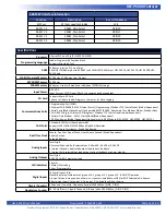
Page 60: ...rial Ports Model dependent Configurable RS232 RS485 Structured Text Modbus Master Modbus Slave 1 Wi Fi 802 11b g n Wireless LAN Program Modbus TCP VersaCloud model dependent 1 Cellular Data Modem 3G V VersaCloud Model Dependent 1 GPS Positioning Model Dependent Optional plug in GPS Module HEC P5010 HEC P5200 HEC P5210 CAN Ports 2 Standard CAN Ports board powered Supports SAE J1939 NMEA 2000 and Op...

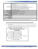
Page 61: ...red Text using Divelbiss EZ LADDER Toolkit Mounting Panel Mount using screws Size 6 3 Wide x 7 92 Length x 2 15 Tall Excluding antennas Operating Temperature 40 80 C SEE NOTE 2 Cellular Antenna Mating Connection SMA Wi Fi Antenna Mating Connection RPSMA Antennas must be electrically isolated from panel ground common If not isolated damage will result NOTE 1 2 Amps Total per point up to 55 C 8 Amps...

Reviews: