VersaGateway User’s Manual
Document #: 2015006.1.pdf
PAGE 12 of 44
Divelbiss Corporation • 9778 Mt. Gilead Road • Fredericktown, Ohio 43019 • 1-800-245-2327 • www.divelbiss.com
Device Features
Input Power
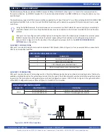
The VersaGateway main power is supplied by the pluggable PWR IN terminal block. Refer to Figure 1-5 for location of the PWR IN
terminal block (Item 1). Input current can vary greatly based on model and mode of operation.
The VersaGateway power is NOT fused on-board. It is recommended fusing the +VIN power using an external fuse. Failure
to protect the VersaGateway may result in damage.
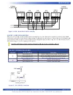
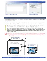
In addition to the PWR IN terminal block, the VersaGateway provides an alternative power input port, AUX PWR IN (Item 2). This
port is a Barrel Connector that accepts a 2.1mm ID / 5.5mm OD mating power plug. This is ideally suited for the use of a wall-pack/
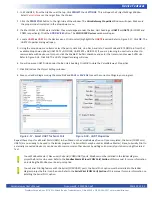
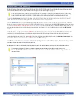
mount type power supply. Figure 2-1 provides connection details (Pin 1 = +VDC / Pin 2 = -(Common) / Pin 3 = No Connect).
PWR / Power Input -Output Pin-Out
PIN ID
CONNECTION
+
+ DC Input (9-32VDC)
-
- Input (DC Common)
EARTH GROUND
Figure 2-1 - AUX PWR IN Connections Info
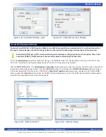
cui
.com
CUI Inc
│
MODEL:
PJ-102A
│
DESCRIPTION:
DC POWER JACK
date
01/08/2015
│
page
2 of 3
3.0
0.421
10.7
4.7
0.118
0.185
3.0 0.118
3.0 0.118
0.421
10.7
3.0 0.118
0.138
(TYP)
0.185
4.7
3.5
6.50 0.256
2
3
1
14.4 0.567
3.50 0.138
0.433
6.50 0.256
0.039
(3 PLCS)
0.354
9.0
1.00
11.0
2.0 0.079
2
1.00X1.60
TOP VIEW
3
PCB LAYOUT
(3 PLCS)
1
MECHANICAL DRAWING
MATERIAL
PLATING
center pin
copper
nickel
terminal 1
brass
tin
terminal 2
copper alloy
tin
terminal 3
brass
tin
plastic
PBT
units: mm[inches]
tolerance:
X.X ±0.2mm
X.XX ±0.1mm
X.XXX ±0.05mm
Note:
1. All specifications measured at 10~35°C, humidity at 45~85%, under standard atmospheric pressure, unless otherwise noted.
SCHEMATIC
3
2
1
Model
PJ-102A
Center Pin
Ø2.0 mm
MATING PLUG
Jack Insertion Depth: 9.0 mm
For more information, please visit the product page.
Programming Port
As the VersaGateway must be programmed with a ladder diagram, function block and structured text program to operate, it must
be programmed using EZ LADDER Toolkit via the programming port (Item 3).
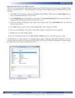
The VersaGateway require a programming cable to connect the device to a computer (with EZ LADDER Toolkit). The programming
cable is a standard 9 pin d-sub female to audio (barrel) connector. The part number for the programming cable is SI-PGM and must
be ordered separately (not included with VersaGateway or EZ LADDER Toolkit).
Connect the audio (barrel) jack to the PGM connector of the VersaGateway Device and the DB9 connector to the computer run
-
ning EZ LADDER Toolkit. Refer to Figure 1-5 for the PGM (programming port) connector location (Item 3). The VersaGateway is now
ready to communicate to EZ LADDER Toolkit running on the PC.
If the computer does not have a serial port, a USB to Serial adapter must be used. We recommend a high quality
USB-Serial adapter similar to the
138-106865
that we offer separately.
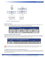
User Programmable Switch
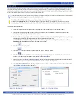
The VersaGateway has one on-board programmable selector switch (SW1-3). Refer to Figure 1-5 for locating SW1. This switch’s state
may be read (Off = 0 / On = 1) as a digital input in the ladder diagram program. This switch may be used for any function needed in
the ladder diagram such as a software configuration switch or configurable
option
. This input is accessed in the ladder diagram us
-
ing the USR_IN boolean variable. This variable is automatically created when the VersaGateway target (VCG-X-X-X) is selected in the
Project Settings


