VersaGateway User’s Manual
Document #: 2015006.1.pdf
PAGE 16 of 44
Divelbiss Corporation • 9778 Mt. Gilead Road • Fredericktown, Ohio 43019 • 1-800-245-2327 • www.divelbiss.com
Device Features
CAN Port 1 - NMEA COMPLIANT
The VersaGateway Device provides an NMEA Compliant CAN port (CAN Port 1) (See Figure 1-5, Item 8) for communications to /
from external devices. As a NMEA Compliant Port, it can be connected directly to an NMEA 2000 bus or it may be used as any stan
-
dard CAN port.
The VersaGateway supports all CAN communications supported by it’s base P-Series PLC on a Chip, including SAE J1939, NMEA 2000
and Divelbiss OptiCAN. Refer to the P-Series EZ LADDER Toolkit manual for details on supported CAN protocols and how to imple
-
ment them.
Using the OptiCAN network, the VersaGateway can communicate to other Divelbiss I/O devices and programmable logic
controllers (based on PLC on a Chip). Multiple devices may be connected to the CAN port provided they all use the same
protocol.
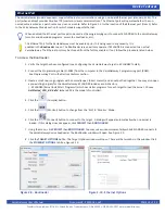
CAN port 1 can be configured with multiple options including the choice of on-board power (standard) or external power
(NMEA Compliant) as well as the choice of external supply voltage. These options are all configured using on-board
jumpers. Refer to Figure 1-5 for the location of the configuration jumpers. Refer to the
JUMPER CONFIGURATION
SETTINGS
later in this section.
CAN PORT 1 CONNECTIONS
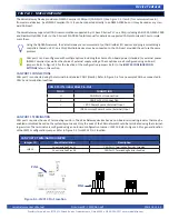
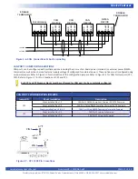
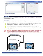
CAN port 1 is connected using the terminal block labeled CAN1 (Item 8). Refer to Figure 2-6 for an example CAN bus connected to
CAN 1 and termination locations.
CAN PORT 1 TERMINATION
CAN port 1 requires the use of terminating resistors. The VersaGateway devices have an on-board terminating resistor that may be
enabled or disabled based on the system layout needs. Only the ends of the CAN network should be terminated using the terminat
-
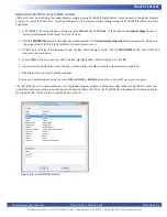
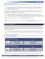
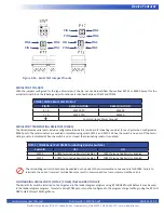
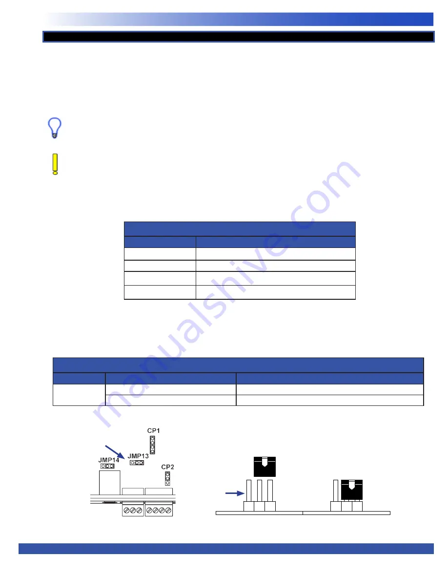
ing resistors. The terminator is configured using an on-board configuration Jumper - JMP13. Refer to Figure 1-5 for general location
of the JMP13 configuration jumper. Refer to Figure 2-5 for JMP 13 Pin 1 location.
CAN PORT 0 TERMINATOR JUMPER
Jumper ID
Shunt Installation
Description
JMP13
Shunt installed Pins 1-2
CAN Port 1 Terminating Resistor Disabled
Shunt installed Pins 2-3
CAN Port 1 Terminating Resistor Enabled
CAN 0 Port Terminal Block Pin-Out
PIN ID
CONNECTION
H
CAN Port 1 HI connection
L
CAN Port 1 LO connection
+
+VDC Power Source (External) Input
-
- (DC Common) Power Source (External) Input
PIN 1
Figure 2-5 - JMP13 Pin 1 Location
PIN 1


