VersaGateway User’s Manual
Document #: 2015006.1.pdf
PAGE 18 of 44
Divelbiss Corporation • 9778 Mt. Gilead Road • Fredericktown, Ohio 43019 • 1-800-245-2327 • www.divelbiss.com
Device Features
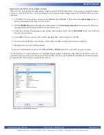
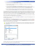
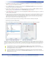
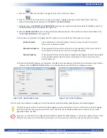
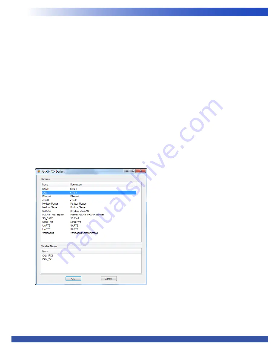
Figure 2-8 - Install CAN1 Device
INSTALLING CAN PORT 1 IN EZ LADDER TOOLKIT
CAN Port 1 must be installed in the ladder diagram program using EZ LADDER Toolkit before it may be used in the ladder diagram
program. To install the CAN1 port, it must be configured in the program’s target settings using the EZ LADDER Toolkit’s Project Set
-
tings Menu.
1. In EZ LADDER, from the File Menu at the top, click
PROJECT
then
SETTINGS
. This will open the
Project Settings
Window.
Select
VersaGateway
as the target from the choices.
2. Click the
PROPERTIES
button to the right side of the window. The
VersaGateway Properties
Window will open. Make sure
the proper model (VCG-X-X-X) is selected in the drop-down menu.
3. If CAN1 were installed, it would appear under the Bus, CAN heading as CAN1. Click the
ADD DEVICE
button. The
PLCHIP-PXX
Devices
window will open.
4. Locate
CAN1
in the
Devices
pane. Click to select (highlight) CAN1. Refer to Figure 2-8. Click
OK
.
5. You will now see CAN1 listed under the Bus - CAN heading. Click
OK
to close the
VersaGateway Properties
.
7. Click
OK
to close the
Project Settings
window
.
8. Save your ladder diagram using the menu
FILE
and
SAVE
or
SAVE AS
to save the current settings in your program.
The CAN (CAN1) port is now available to use in the ladder diagram program. Additional configurations for OptiCAN or other sup
-
ported CAN networks may be required to use the CAN port. Refer to the P-Series EZ LADDER Toolkit Manual for details on imple
-
menting OptiCAN, J1939 or other supported CAN networks.


