VersaGateway User’s Manual
Document #: 2015006.1.pdf
PAGE 24 of 44
Divelbiss Corporation • 9778 Mt. Gilead Road • Fredericktown, Ohio 43019 • 1-800-245-2327 • www.divelbiss.com
Device Features
PIN 6
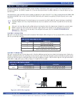
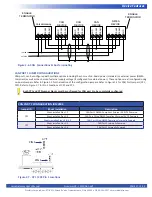
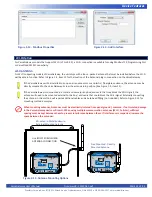
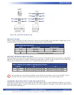
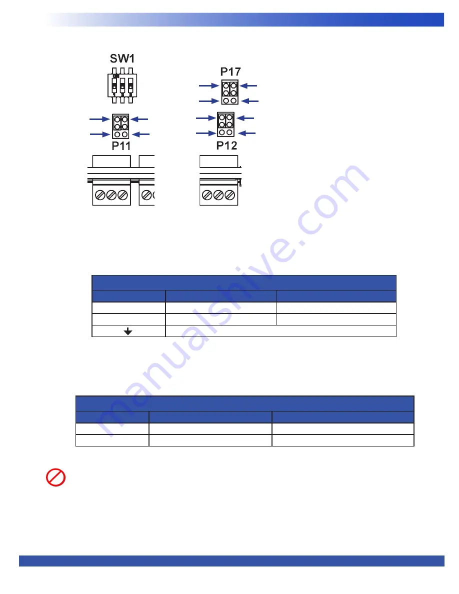
Figure 2-16 - Serial Port Jumper Pin-outs
PIN 2
PIN 5
PIN 1
PIN 6
PIN 2
PIN 1
PIN 5
PIN 2
PIN 6
PIN 5
PIN 1
SERIAL PORT PIN-OUTS
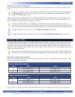
With the jumpers configured for the type of serial port, the pin-out can be identified. Choose from RS232 or RS485. Except for the
actual terminal block, the labeling and pin functions are identical between COM2 and COM3.
SERIAL PORT TERMINATING RESISTORS (RS485)
The VersaGateway serial ports include configurable terminators (on-board terminating resistors) for each port when configured as
RS485 ports. These terminators are enabled or disabled using switch SW1-1 and SW1-2. When the switch is open or off, the termi
-
nating resistor is disabled. When the switch is on or closed, the terminating resistor is enabled.
The terminating resistor should only be enabled on the ends of the communications bus and only for RS485. Failure to
terminate the ends or incorrect terminations may result in communications loss or communications errors.
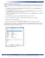
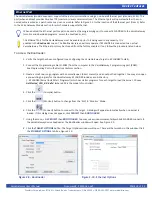
CONFIGURING SERIAL PORTS (COM2 / COM3) IN EZ LADDER TOOLKIT
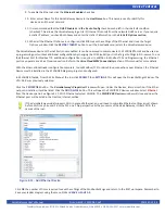
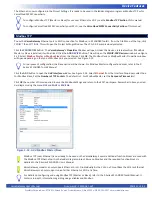
The Serial Ports must be installed on the target and in the ladder diagram program using EZ LADDER Toolkit before it may be used
in the ladder diagram program. To install a Serial/COM port, it must be configured in the program’s target settings using the EZ LAD
-
DER Toolkit’s Project Settings Menu.
COM2 / COM3 Serial Port Pin-Out
PIN ID
RS232 FUNCTION
RS485 FUNCTION
R / B
RS232 RXD
RS485B
T / A
RS232 TXD
RS485A
Common (Input Power Ground)
COM2 / COM3 Serial Port RS485 Terminating Resistor Switches
Switch ID
OFF
ON
SW1-1
COM2 Terminating Resistor Disabled
COM2 Terminating Resistor Enabled
SW1-2
COM3 Terminating Resistor Disabled
COM3 Terminating Resistor Enabled


