VersaGateway User’s Manual
Document #: 2015006.1.pdf
PAGE 36 of 44
Divelbiss Corporation • 9778 Mt. Gilead Road • Fredericktown, Ohio 43019 • 1-800-245-2327 • www.divelbiss.com
Device Features
2. Click the
PROPERTIES
button to the right side of the window. The
VersaGateway Properties
Window will open. Make sure
the proper model is selected in the drop-down menu.
3. Click the
ADD DEVICE
button. The
PLCHIP-PXX Devices
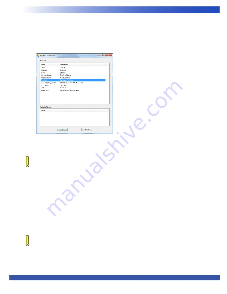
window will open. Locate the
OptiCAN
in the Devices pane
of this window.
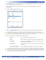
4. Click / select
OptiCAN
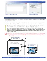
(highlight). Refer to Figure 2-33.
5. Click
OK
. The
OptiCAN Properties
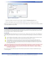
Window will open. The settings in this dialog box will configure the OptiCAN network
Any OptiCAN network implementation will be dependent upon the actual applications needs and requirements.
Knowledge of the OptiCAN network is required to configure the communications. Refer to the P-Series EZ LADDER Toolkit
Manual for details on how the OptiCAN network functions, how to implement it and how to use it.
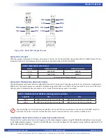
6. Enter the setup information for the OptiCAN network. Refer to Figure 2-34.
CAN Port:
Select the CAN Port to use the OptiCAN network on.
Node ID:
Network address (ID) for identify this equipment on the OptiCAN network.
Broadcast Rate:
Rate at which network registers are transmitted across the network (when
based on interval). In milliseconds.
Send Heartbeat:
Check this box if this device is to send the network heartbeat (only one device
per network).
Common Broadcast Registers:
Used to configure the Broadcast trigger of the Status and Error registers.
The information regarding OptiCAN shown here is for basic example only. Implementation is dependent upon the actual
application requirements. For more information regarding OptiCAN communications including installation configuring and
using, refer to the P-Series EZ LADDER Toolkit Manual. The P-Series EZ LADDER Toolkit Manual (OptiCAN) section should
be read before an attempt to implement an OptiCAN network.
Figure 2-33 - PLCHIP-PXX Devices - OptiCAN

